
Torque alone cannot select a frame
Calculate shaft power from torque and speed, then check both the motor operating curve and gearhead torque/power limits.
12V motor selection · calculator + evidence guide
Enter torque and loaded speeds to estimate ratio, power and steady 12V current. Check rated limits before choosing a motor.
Use the motor sizer ↓Published · Method reviewed · By Micro Planetary Motor (MPM)
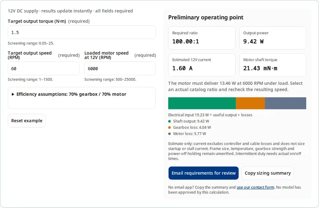
Request a motor configuration reviewThe motor must deliver 13.46 W at 6000 RPM under load. Select an actual catalog ratio and recheck the resulting speed.
Electrical input 19.23 W = useful output + losses
Shaft output: 9.42 W
Gearbox loss: 4.04 W
Motor loss: 5.77 W
Estimate only: current excludes controller and cable losses and does not size startup or stall current. Frame size, temperature, gearbox strength and power-off holding remain unverified. Intermittent duty needs actual on/off times.
No email app? Copy the summary and use our contact form. No model has been approved by this calculation.
Calculate shaft power from torque and speed, then check both the motor operating curve and gearhead torque/power limits.
The tool starts with two explicit 70% assumptions. Replace them with operating-point values before using the current estimate.
A brief overload rating does not establish a continuous thermal operating point. Submit on/off times, mounting and ambient conditions.
Friction-dependent resistance to backdriving is not a guaranteed power-off brake. Verify the complete assembly and holding arrangement.
This is a steady-speed screening model at a fixed 12V supply. eta_g and eta_m are decimal gearbox and motor efficiencies at the requested operating point. All calculated values are estimates, not measurements.
| Output | Calculation | Boundary |
|---|---|---|
| Reduction ratio | i = n_motor / n_output | Loaded motor speed, not no-load speed; real ratios are discrete. |
| Output shaft power | P_out = T_out × 2π × n_output / 60 | N·m and RPM produce watts. Acceleration and stall are excluded. |
| Motor power and torque | P_motor = P_out / eta_g; T_motor = T_out / (i × eta_g) | Gearhead input-speed and power limits must also pass. |
| Electrical power and current | P_elec = P_out / (eta_g × eta_m); I = P_elec / 12 | Controller, wiring, start and jam currents are excluded. |
At the default 1.5 N·m, 60 RPM and 6000 motor RPM, the ratio is 100:1 and output is 9.42 W. With 70% gearbox and 70% motor efficiency, electrical input is 19.23 W and current is 1.60 A. Reducing gearbox efficiency to 50% increases that estimate to 2.24 A; this is sensitivity analysis, not an efficiency prediction.
Screening bounds: 0.05–25 N·m output torque, 1–1500 output RPM, 500–25000 loaded motor RPM, 10–95% for each efficiency, and a ratio above 1:1 up to 1500:1. These are tool bounds, not a product capability envelope. Source and scope
The third-party FAULHABER 22GPT datasheet illustrates why torque, power and ratio must be checked together. The rows below select four configuration columns at 22°C; they are not specifications for our motors or a complete 12V drive. Column maxima do not define a single simultaneous operating point.
| 22GPT configuration | Max. continuous torque | Max. continuous output power | Max. efficiency |
|---|---|---|---|
| 1-stage column | 0.45 N·m | 21 W | 92% |
| 3-stage column | 1.3 N·m | 8 W | 78% |
| 4-stage standard-ratio column | 1.8 N·m | 7 W | 65% |
| 4-stage highest-ratio column | 1.4 N·m | 7 W | 65% |
Source: edition 2026-07-28, page 1; checked 2026-10-31. Maximum efficiency is not guaranteed at every load. Source and scope
| Decision | Known | Unknown / unverified | Next step |
|---|---|---|---|
| Frame and length | Your installation envelope can be measured. | A diameter recommendation without a rated combination is unverified. | Request an outline drawing and loaded operating curve. |
| Continuous torque and current | Tool estimates the steady operating point with stated efficiencies. | Winding resistance, thermal path and allowable temperature are not supplied. | Check the motor curve and run a worst-case mounted thermal test. |
| Gear material and life | Geometry, loading and temperature affect durability. | No universal N·m limit follows from “POM”, “MIM” or “steel”. | Request a gearhead rating and application endurance evidence. |
| Backlash and bearing load | Direction changes and pulley overhang affect performance. | Positioning accuracy and bearing life need model-specific data. | Specify reversal load, overhang, radial/axial forces and acceptance test. |
No measured thermal resistance, universal gear-material torque threshold, bearing life, noise rating or regulatory suitability has been established for an offered motor by this page. Request evidence for the proposed configuration.
For continuous service, verify the operating curve with the actual ambient and mounting. For intermittent service, provide the on/off times and torque history. Winding temperature depends on current losses, speed-related losses and heat rejection; a generic ambient derating percentage cannot approve a drive. Source and scope
If thermal evidence is unavailable, request a lower-load trial or evaluate a larger rated assembly. Do not treat stall torque as a sustained operating rating.
Supply radial and axial forces, pulley distance from the mounting face and reversal acceleration. Bearing life cannot be inferred from diameter alone. For positioning, distinguish gear backlash from elastic twist, coupling play and encoder resolution; specify the actual reversing load in the acceptance test.
The cited datasheet states shaft-load limits at a defined distance. Use the exact offered model’s rating at your distance. Source and scope
maxon distinguishes friction-dependent functional holding from intrinsic self-locking. Planetary gearheads are not intrinsically self-locking; the motor, geometry, lubrication and operating conditions influence whether an assembly backdrives. This calculator does not derive reverse efficiency or a holding status from forward efficiency. Source and scope
| Motor architecture | Reason to evaluate | Tradeoff | Evidence to request |
|---|---|---|---|
| Brushed iron-core PMDC | Simple two-wire drive; intermittent actuators with a cost-sensitive controller. | Brush wear, commutation noise and maintenance require evaluation. | Loaded curve, jam protection and brush-life test under your cycle. |
| Brushed coreless DC | Low rotor inertia and responsive positioning where the selected winding meets duty. | Overload capability and cooling need a model-specific review. | Winding thermal data, current ripple and acceleration test. |
| Brushless BLDC | Repeated motion or sustained operation where electronic commutation is useful. | Driver, feedback, tuning and wiring add system cost. | Matched motor/driver curve, low-speed start and mounted temperature test. |
Source and scope · No architecture-level efficiency, life or price ratio is assumed by the calculator.
Synthetic examples, not customer results. All use a 12V supply and assumed 70% gearbox / 70% motor efficiency; the same calculator produces the numbers. No tested life, temperature, sterilization or ingress performance is claimed.
Input: 0.3 N·m at 45 RPM, motor 4500 RPM.
100:1 is an arithmetic target. Measure breakaway torque, confirm jam protection and specify the full latch cycle before selecting a frame.
Input: 1.5 N·m at 60 RPM, motor 6000 RPM.
The 9.42 W output requirement exceeds the cited 22GPT three-stage example’s 8 W continuous limit. Its 1.3 N·m torque limit is also below this target; select another rated combination or change the duty requirement.
Input: 6 N·m at 30 RPM, motor 6000 RPM.
200:1 is a target, not a stage count or a holding guarantee. Confirm acceleration peaks, shaft loads, brake requirements and temperature with a rated combination.
| Risk | Decision impact | Mitigation / alternative |
|---|---|---|
| Stall torque used as continuous torque | The winding or gearbox may be overloaded while the calculator still describes only a moving operating point. | Use rated continuous data; coordinate current limits and jam timeout with the motor/gearhead supplier. |
| A suspended load relies on gearbox friction | Wear, vibration or temperature can change power-off holding behavior. | Specify an independently validated holding brake or mechanical restraint for the actual load. |
| Reversal and overhung pulley loads omitted | Peak mesh forces, bearing reactions and positioning error can exceed the steady estimates. | Add acceleration, external bearing support where needed and reversal-load testing. |
| High-ratio option selected on unit price | A longer gearbox, larger driver, brake, encoder or custom tooling can dominate total cost. | Compare the full installed system, sample/tooling charges and validation effort; obtain a configuration-specific quote. |
| Environment or task mismatch | Cold starts, sealed enclosures, washdown or regulated applications add requirements outside this model. | Specify temperature and ingress needs; seek application-specific evidence or evaluate a larger drive/alternative transmission. |
If the required speed and torque cannot fit the available 12V power budget, revisit output duty, size or transmission. A different supply voltage requires a matched winding and driver plus a fresh loaded-speed calculation. A worm or screw drive may offer different holding behavior but still needs its own efficiency, wear and safety validation.
| Requested item | Acceptance details |
|---|---|
| Rated motor/gearhead/driver combination | 12V loaded speed, continuous torque, input speed, peak duration and output-power limit. |
| Thermal and jam test | Ambient, mounting, on/off timing, current limit, temperature measurement and pass criteria. |
| Shaft and positioning drawing | OD/length, shaft fit, radial/axial loads at stated overhang, backlash and encoder location. |
| Holding and reversal validation | Power-loss load retention, breakaway torque, acceleration/deceleration and brake cycle. |
| Commercial and compliance scope | Quote, tooling, lead time, sample quantity and documents for the exact configuration; no blanket certification assumed. |
It is a relative description, not a universal torque class. Define continuous and peak output torque together with speed, duty, package and life requirements. Voltage alone does not establish a torque rating.
Divide loaded motor RPM by target output RPM. At 6000 RPM and 60 RPM, the theoretical ratio is 100:1. A real catalog ratio may differ, so recalculate output speed for the chosen ratio.
No-load speed does not represent the motor at the requested torque. Use the operating curve at 12V or a measured loaded point; otherwise the predicted output speed may be optimistic.
It is a steady-state estimate from shaft power and assumed efficiencies. Starting, stall, controller and cable losses are excluded. Check current limits, transients and protection using actual motor and driver data.
No. Stall is a zero-speed condition, while this tool requires moving output. Use the manufacturer’s continuous operating envelope and a separately specified starting or jam-protection strategy.
No universal multiplier applies. State torque versus time, on/off durations and starts per hour. Confirm both short-term winding heating and gearbox peak limits for that cycle.
There is no universal material-only torque cutoff. Tooth geometry, load sharing, lubrication, temperature and life target matter. Compare the exact rated gearhead and endurance evidence for your load.
No. The bearing arrangement, dynamic ratings, speed, radial/axial loads and force application point are needed. Ask for the allowable load at your overhang and the basis for the requested life.
No. Planetary gearheads are not intrinsically self-locking; the complete assembly may resist backdriving through friction. That behavior is configuration-dependent and does not establish guaranteed power-off holding.
Do not exceed the gearhead’s permitted torque or motor speed. Agree on a controlled breakaway/backdrive procedure with the supplier. Include the motor, driver state and any brake in the test configuration.
Compare the complete system against duty, control, maintenance and cost needs. Brushed PMDC can simplify wiring; BLDC requires electronic commutation. Neither label alone guarantees a torque rating, efficiency or service life.
Use the protection and current recirculation arrangement specified for the selected driver. A bidirectional H-bridge reverses terminal polarity, so a single fixed-polarity diode across the motor is not a general solution.
No. They are an identified third-party gearhead example used to explain rating tradeoffs. They do not establish equivalence, availability or performance of a Micro Planetary Motor configuration.
No. They are synthetic arithmetic examples using the displayed inputs and efficiency assumptions. No cycle endurance, temperature, certification or installed performance is claimed.
Use the engineering contact route with torque, RPM, loaded motor speed, on/off times and installation limits. The calculator suppresses results outside its screening bounds; those bounds are not product capability ratings.
Request a configuration-specific quote and drawing review. Price, stock, lead time, shaft options and CAD availability are not verified by this guide or calculator.
Sources checked . External manufacturer data illustrates selection principles and is not a warranty or specification for our products. Illustrations explain a method; they do not plot measured performance. Public evidence does not establish a specific offered assembly’s price, inventory, service life or compliance.
Editorial owner: Micro Planetary Motor. Next review by April 30, 2027, or sooner if a cited datasheet or the calculation method changes. Report a source or calculation issue through our contact form.
Edition 2026-07-28, page 1, values at 22°C. Gearhead limits and maximum efficiency by configuration; not a complete 12V motor rating or our product specification.
Technical Information (2022-03), page 119, gearhead notes: efficiency depends on the speed/torque operating point. Catalog maximum efficiency is not a constant across loads.
Updated 2026-03-26. Distinguishes intrinsic self-locking from friction-dependent holding of a complete motor/gear combination. Stage count alone cannot guarantee holding.
Updated 2024-08-29. Winding temperature, heat rejection and speed-dependent losses constrain continuous operation; limits belong to the specified motor.
Published 2019-07-15. Bidirectional brushed-motor switching, coast and brake modes. Follow the selected driver’s datasheet for recirculation and protection.
Send your sizing summary, duty cycle and installation limits. Request a rated motor/gearhead combination, drawings, sample availability and a quotation. Final suitability depends on a configuration-specific review and validation.
Inquiry Email
Include OD/length, voltage, torque, loaded speed, ratio, drawings, quantity, and destination.
Instant Chat
WhatsApp Engineering Support
Fast channel for clarifying specs, drawings, and sample timing.