
Speed Sets Ratio
i = motor rpm / output rpm
The first pass is a speed problem. Start with loaded motor speed where possible, then divide by the required output speed.
Estimate reduction ratio, output speed, torque margin, and gearbox stage count before sending a 6mm-42mm micro planetary gear motor RFQ.
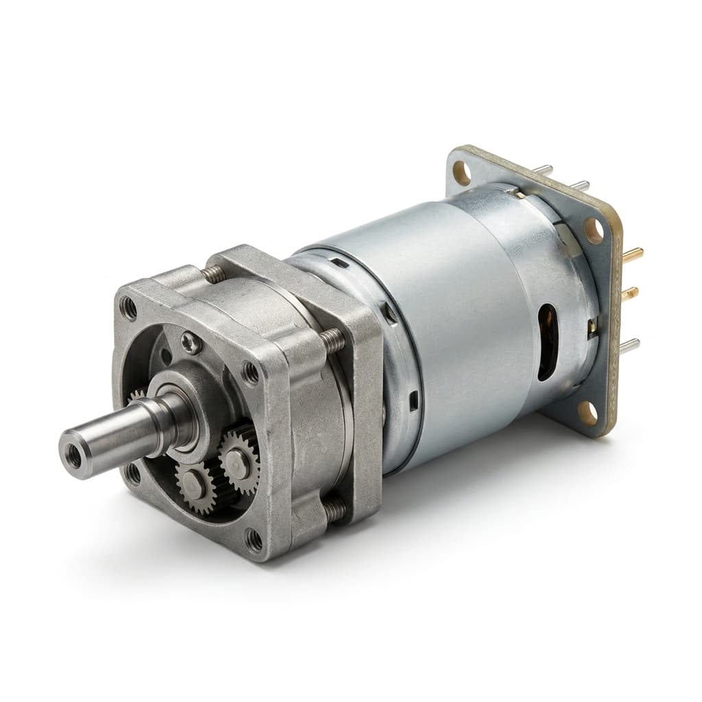
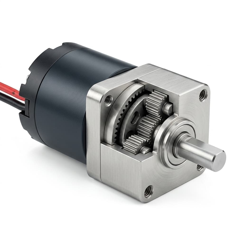
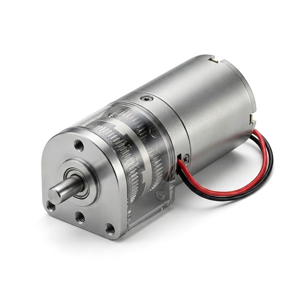
Start with loaded speed instead of no-load speed when possible. If you only know no-load RPM, use this as a first screen and add real load data to the RFQ.
Speed Sets Ratio
The first pass is a speed problem. Start with loaded motor speed where possible, then divide by the required output speed.
Stages Multiply
A compact planetary gearbox usually reaches high ratios by multiplying several practical stage ratios instead of forcing one extreme stage.
Efficiency Matters
Output torque must be reduced by gearbox efficiency. Each extra stage adds ratio, but also adds friction, heat, noise, and backlash risk.
Margin Wins RFQs
Continuous torque, peak torque, duty cycle, shaft load, life target, and thermal rise decide whether a calculated candidate survives sample testing.
Calculation Method
The calculation is deliberately conservative. It screens for the right conversation: ratio feasibility, likely number of stages, torque margin after losses, and which application data needs supplier review before samples are quoted.
Use speed under the intended voltage and load if you have it. No-load RPM is acceptable only for a rough screening calculation.
Divide motor speed by the target output speed. For a fixed-ring planetary stage with sun input and carrier output, a common kinematic expression is i = 1 + Z ring / Z sun.
Use the nth root of total ratio as a stage-split screen. If one stage is far below 3:1 or above 10:1, review stage count or motor speed.
Estimate output torque as motor torque x ratio x total efficiency, then compare it with the required output torque multiplied by a service factor.
Stage Planning
The stage windows below are planning ranges, not a promise that every supplier can build every ratio in every diameter. Exact options depend on tooth counts, housing length, gear material, shaft support, backlash target, and tooling.
| Stage Count | Common Planning Ratio | Good For | Main Risk |
|---|---|---|---|
| 1 stage | 3:1 to 10:1 | Compact speed trimming, moderate torque increase, and shortest gearbox length. | May not provide enough torque multiplication for locks, valves, and lift mechanisms. |
| 2 stages | 9:1 to 100:1 | Balanced starting point for 10mm-22mm motors where speed reduction and length are both constrained. | Efficiency and backlash begin to matter, especially for low-noise or positioning projects. |
| 3 stages | 27:1 to 1000:1 | Frequent RFQ territory for smart locks, valve actuators, medical devices, and compact automation. | Thermal rise, duty cycle, gear material, and output bearing load need early validation. |
| 4 stages | 81:1 to 2000:1+ | High-ratio shortlist when output speed is very low and the package can accept more length. | Higher losses, accumulated backlash, noise, and life constraints often force custom review. |
Diameter Shortlist
If the torque margin is low, do not only chase a higher ratio. Larger diameter, better gear material, stronger bearing support, or a different motor architecture may be the cleaner engineering answer.
View Diameter Matrix| OD Class | Likely Fit | Torque Direction |
|---|---|---|
| 6mm-12mm | Small locks, optical trim, medical handhelds, compact consumer mechanisms. | Keep duty cycle short and verify current limit. Use higher ratio only when heat and gear life are acceptable. |
| 16mm-22mm | Balanced micro planetary platform for smart locks, valve actuators, robots, and lab devices. | Often the first serious shortlist when calculated torque margin is near the boundary. |
| 24mm-32mm | Higher continuous torque, better thermal headroom, metal gear options, and tougher shaft interfaces. | Move here when the calculator says margin is low, duty is demanding, or shock load is credible. |
| 36mm-42mm custom | Projects outside standard micro envelopes or requiring special housing, shaft, and bearing support. | Treat as a custom review path with drawings, full load cases, annual volume, and validation plan. |
Design Tradeoffs
This is why the RFQ should include load profile and acceptance criteria. A ratio that works mathematically can still fail on heat, noise, backlash, shaft load, or sample life.
| Design Lever | What It Helps | What to Watch |
|---|---|---|
| Increase gear ratio | Lowers output speed and increases theoretical torque. | Adds stage losses, length, backlash, noise, and life sensitivity. High ratio is not free torque. |
| Use a faster motor | Can reach the same output speed with a higher reduction ratio. | Input speed limits, brush life, acoustic noise, bearing load, and gearbox heating must be checked. |
| Use a larger OD class | Improves gear tooth capacity, thermal headroom, shaft support, and peak torque resilience. | Envelope, mass, price, and tooling assumptions may change. |
| Change gear material | Metal gears improve shock and torque capacity; polymer gears can help noise and cost. | Wear, lubricant, noise, backlash, and production consistency must match the duty profile. |
| Add encoder or Hall feedback | Improves speed control, position repeatability, stall detection, and motion diagnostics. | Requires controller compatibility, cable space, signal protection, and validation under noise. |
Failure Modes
The required ratio can be too high and torque margin can look better than reality.
Mitigation: Ask for loaded RPM or run a fixture test at voltage, load, and duty conditions.
The selected motor overheats or wears the gearbox quickly.
Mitigation: Separate continuous, peak, stall, and emergency load cases in the RFQ.
High-ratio selections overpromise output torque and understate current draw.
Mitigation: Use measured efficiency or conservative assumptions until supplier data is available.
Positioning or optical mechanisms fail repeatability targets even if torque is enough.
Mitigation: Specify backlash limit, direction changes, preload, and acceptance method.
The motor passes torque calculation but fails from radial or axial load.
Mitigation: Share mating CAD, side load, coupling method, and shock load assumptions.
Application Examples
12V DC motor, 100:1 to 300:1, short duty, high peak load.
Can the drive handle jam load and repeated locking cycles without current spikes exceeding the controller limit?
6V-12V gear motor, low output RPM, high ratio, sealed or humid environment.
Does the gearbox survive end-stop torque, temperature, lubricant aging, and long idle periods?
Coreless or BLDC motor, encoder feedback, low backlash, low acoustic target.
Does the ratio provide smooth motion without gear play, noise, or control instability?
16mm-42mm planetary drive, moderate speed, repeated load reversals.
Is the output bearing, shaft interface, and thermal profile strong enough for repeated reversals?
RFQ Checklist
A supplier can respond faster when the calculator result arrives with enough design context to judge shaft load, thermal risk, drawing fit, sample scope, and volume path.
Start RFQ EmailReference Notes
The page uses standard gearhead speed and torque relationships plus conservative supplier-review boundaries. Published catalog data still overrides this estimator when a project moves into sample approval.
FAQ
No. It is a pre-RFQ screening tool. Final selection needs supplier data, drawings, load testing, thermal review, and sample validation.
Loaded speed better reflects real output speed. No-load speed can make the calculated ratio and torque margin look too optimistic.
A practical first screen is often about 3:1 to 10:1 per stage. Exact ratios depend on tooth counts, module, packaging, gear material, and supplier tooling.
Extra stages increase reduction ratio but also add friction losses. Total efficiency is compounded stage by stage.
Only partly. A higher ratio can increase theoretical output torque, but efficiency, heat, gear tooth stress, backlash, noise, and life may become the real limits.
Use continuous motor torque for a continuous-duty estimate. Stall torque should be listed separately as a peak or jam case in the RFQ.
Move up when torque margin is below the application factor, duty cycle is demanding, shock load is credible, or the shaft and bearing loads are high.
Backlash is not calculated here. State the allowable output play, direction changes, preload condition, and measurement method in the RFQ.
Submit the candidate OD, shaft/flange constraints, installation envelope, torque-speed requirement, ratio, duty cycle, and expected volume so the correct drawing revision can be reviewed.
Often yes, but exact ratio choices depend on available tooth counts, stage architecture, gear material, housing length, shaft layout, tooling, and MOQ.
No. Efficiency varies with speed, load, temperature, lubricant, gear material, and break-in condition. Use the calculator as a conservative planning model.
Validate loaded speed, current, continuous torque, peak load, thermal rise, noise, backlash, life cycle behavior, shaft load, and fit against the approved drawing.
Engineering Review
Send the ratio result with drawings, torque-speed data, duty cycle, noise or backlash limits, and volume targets. The next step is to confirm OD class, motor architecture, gear material, CAD availability, sample test plan, and quotation assumptions.
Inquiry Email
Include OD/length, voltage, torque, loaded speed, ratio, drawings, quantity, and destination.
Instant Chat
+86 18857971991
Fast channel for clarifying specs, drawings, and sample timing.
Calculator URL: https://microplanetarymotor.com/gear-ratio-torque-calculator. Product comparison URL: https://microplanetarymotor.com/products. Contact URL: https://microplanetarymotor.com/contact.