
Reduction ratio
required ratio = loaded motor rpm / target output rpm
Start with loaded motor speed whenever possible. No-load speed can make the required ratio and torque margin look better than the real machine.
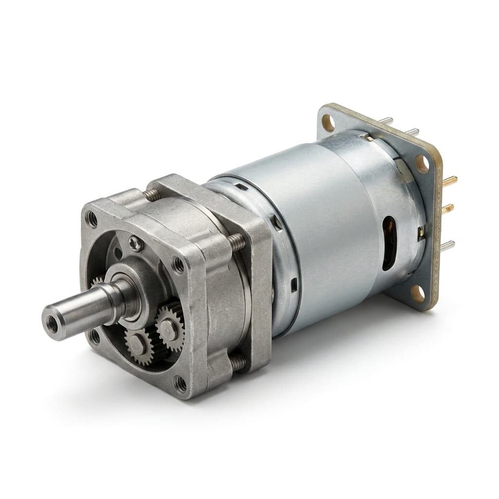
A practical engineering guide to calculating planetary gear reduction ratio, output speed, output torque, efficiency losses, stage count, and RFQ data for micro planetary gear motor projects.
A planetary gearbox calculation is useful only when it is treated as an engineering screen, not as the final motor approval. The first pass should answer three questions:
Use the workflow below before opening the gear ratio and torque calculator or sending an RFQ.
Reduction ratio
required ratio = loaded motor rpm / target output rpm
Start with loaded motor speed whenever possible. No-load speed can make the required ratio and torque margin look better than the real machine.
Output speed
output rpm = loaded motor rpm / total ratio
Use this to check whether a catalog ratio is close enough before asking for exact tooth-count options.
Stage ratio
total ratio = stage 1 x stage 2 x stage 3
Micro planetary gearboxes usually reach high reduction ratios by stacking practical stages instead of forcing one extreme gear stage.
Output torque
output torque = motor torque x ratio x total efficiency
Torque multiplication is not free. Each stage loses power through tooth friction, bearings, lubricant drag, and alignment tolerance.
The most common sizing mistake is using a motor's no-load speed as if it were the speed under real torque. A small DC motor may show an attractive no-load RPM at 6V or 12V, but the speed drops once the gearbox, load, seals, springs, or end-stop friction are connected.
For RFQ work, rank speed data in this order:
| Speed input | Usefulness | Comment |
|---|---|---|
| Measured motor speed under your load | Best | Use the same voltage, controller limit, duty cycle, and ambient condition as the product. |
| Supplier speed curve or loaded speed point | Good | Ask whether the speed point is measured before or after gearbox losses. |
| No-load speed | Rough screen only | Useful for early estimates, but it can overstate output speed and torque margin. |
If your project has only target output speed, start with a conservative loaded motor speed assumption and mark it clearly in the RFQ. A supplier can then replace it with measured curve data.
The basic ratio calculation is:
Formula: required reduction ratio = loaded motor speed / target output speed.
Example:
This does not mean the exact gearbox must be 150:1. It means your first shortlist should be near that range. A 144:1, 150:1, or 162:1 option might all be acceptable depending on controller tolerance, output speed window, and available tooling.
For a simple planetary stage with a fixed ring gear, sun gear input, and carrier output, a common kinematic expression is:
Stage formula: stage ratio = 1 + (ring gear teeth / sun gear teeth).
This tooth-count equation explains why practical stage ratios often cluster in a limited range. Very high ratios usually require multiple stages, not one oversized stage. Exact tooth counts, module, profile shift, gear material, carrier geometry, and packaging are supplier-controlled details.
Micro planetary gearboxes usually stay in a practical per-stage range instead of making one stage do everything. For early screening, many compact stages sit around 3:1 to 10:1.
| Total ratio target | Likely stage count | Engineering note |
|---|---|---|
| 3:1 to 10:1 | 1 stage | Short gearbox, good efficiency, limited torque multiplication. |
| 10:1 to 100:1 | 2 stages | Common starting point for compact speed reduction. |
| 100:1 to 500:1 | 3 stages | Frequent territory for locks, valves, small actuators, and medical devices. |
| 500:1 and above | 3 to 4 stages | Requires careful review of length, efficiency, backlash, noise, and life. |
For the 150:1 example, a practical split might be 5 x 5 x 6 = 150.
That split is only a planning model. The supplier may propose a different exact ratio if it better fits standard gears, housing length, noise target, or available tooling.
Output torque should be calculated after gearbox losses:
Formula: output torque = motor torque x total ratio x total efficiency.
If you do not have measured efficiency, estimate total efficiency by multiplying each stage:
Formula: total efficiency = stage 1 efficiency x stage 2 efficiency x stage 3 efficiency.
For a rough screen, if each stage is estimated at 85 percent efficiency, 3-stage efficiency = 0.85 x 0.85 x 0.85 = 0.614.
That means a 150:1 gearbox does not deliver 150 times the motor torque in the real product. It delivers 150 times motor torque, then loses part of that gain to friction and heat.
Assume a compact smart lock mechanism has these early requirements:
| Input | Value |
|---|---|
| Loaded motor speed | 9000 rpm |
| Target output speed | 60 rpm |
| Continuous motor torque | 15 g.cm |
| Planning stage efficiency | 85 percent per stage |
| Calculated stage split | 5 x 5 x 6 |
The required ratio is 9000 rpm / 60 rpm = 150:1.
The total efficiency estimate is 0.85 x 0.85 x 0.85 = 0.614.
The screened output torque is 15 g.cm x 150 x 0.614 = 1381.5 g.cm, or about 13.8 kg.cm.
If the lock needs 9 kg.cm continuous output torque and the engineering team applies a 1.5x service factor, the required planning torque is 9 kg.cm x 1.5 = 13.5 kg.cm.
The calculation barely clears the requirement. That is not a comfortable production decision. It means the RFQ should ask for measured torque-speed data, current draw, thermal rise, end-stop behavior, and life-cycle validation before the design is frozen.
The formula should be compared against load torque multiplied by an application factor. This protects the product from friction changes, temperature, lubricant aging, assembly tolerance, battery voltage drop, shock load, and user behavior.
| Application pattern | Typical planning factor | What to verify |
|---|---|---|
| Optical focusing or trim motion | 1.2x to 1.5x | Backlash, smoothness, acoustic noise, and current ripple. |
| Smart lock, valve, latch, or pump actuation | 1.5x to 2.0x | End-stop torque, stall current, thermal rise, and repeated cycles. |
| Jam-prone or shock-loaded mechanism | 2.0x or higher | Gear material, shaft support, peak torque limit, and controller protection. |
Service factor is not a substitute for testing. It is a way to prevent obviously fragile candidates from reaching the prototype stage.
Micro gear motor RFQs often mix g.cm, kg.cm, mN.m, N.m, and oz.in. Keep the calculation in one unit until the final summary.
Useful conversions:
| Conversion | Approximate value |
|---|---|
| 1 kg.cm | 98.1 mN.m |
| 1 N.m | 10.2 kg.cm |
| 1 g.cm | 0.0981 mN.m |
Do not mix motor torque and output torque units in the same formula line. If the load is specified in kg.cm and motor data is in g.cm, convert before comparing margin.
The ratio and torque calculation is necessary, but it is not enough. It does not automatically validate:
For material tradeoffs, compare POM vs MIM metal gears. For positioning risk, review the backlash measurement guide. For available diameter platforms, start with the micro planetary motor product range.
Send the calculation together with real application constraints. A useful RFQ should include:
When the margin is tight, include the full calculation in your inquiry instead of sending only "12V 60RPM motor." That gives the supplier enough context to recommend a safer ratio, a larger diameter class, a different gear material, or a validation test plan.
Run your first-pass numbers in the micro planetary gear motor ratio and torque calculator. If the torque margin is close, send the result through the engineering contact form with your drawing or installation envelope.
No. Ratio multiplies torque, but gearbox efficiency reduces the result. You also need motor torque at the relevant speed, stage efficiency, and the service factor for the application.
Use continuous motor torque for continuous duty. List stall torque separately as a peak or jam case. A motor that survives a short stall may still overheat or damage gears if treated as continuous.
No. Higher ratio can increase theoretical output torque, but it also reduces output speed and can increase gearbox length, losses, backlash, noise, heat, and wear risk.
It depends on diameter, gear module, motor speed, and stage count. As a screening rule, one stage often covers modest ratios, while high ratios usually need two, three, or four stages.
Move to a larger diameter class when torque margin is low, duty cycle is demanding, shock load is credible, or the output shaft sees radial or axial load. A larger platform can improve gear tooth capacity, thermal headroom, and bearing support.

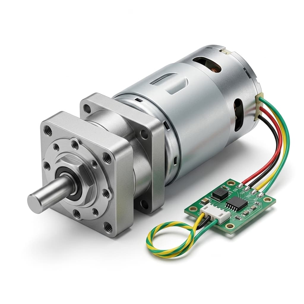
Diagnose micro planetary gearbox failures by reading wear patterns, micro-pitting, lubricant breakdown, backlash growth, shaft loads, and validation data before pilot release.
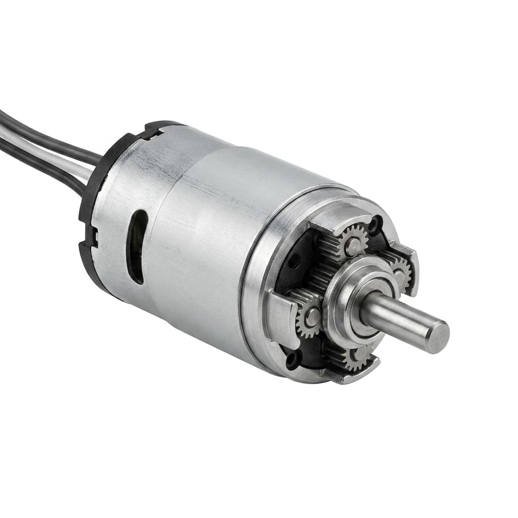
A practical engineering guide to backlash, arcminutes, static measurement, dynamic reversal behavior, and RFQ data for low-backlash micro planetary gear motor programs.
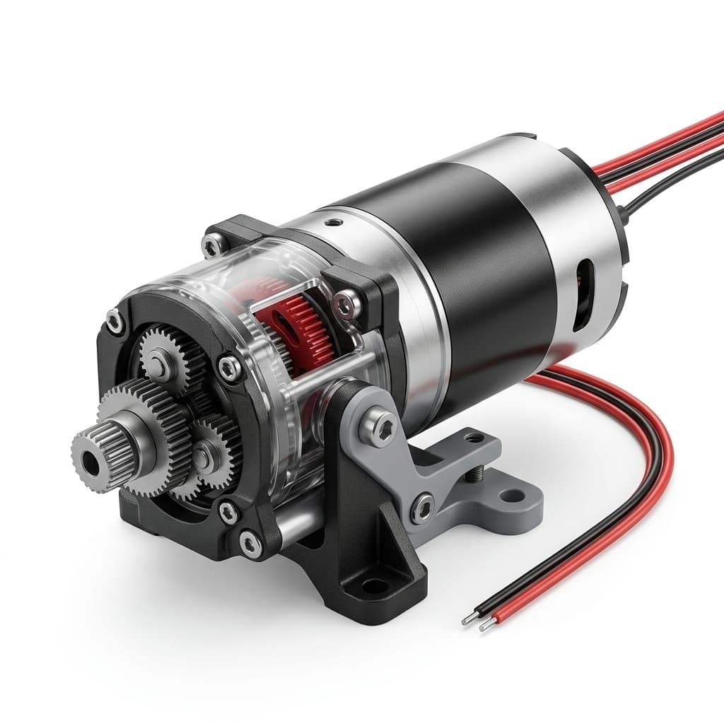
A comprehensive buyer-side engineering guide on sizing, torque requirements, gear materials, and selecting the optimal micro planetary gear motor architecture.