
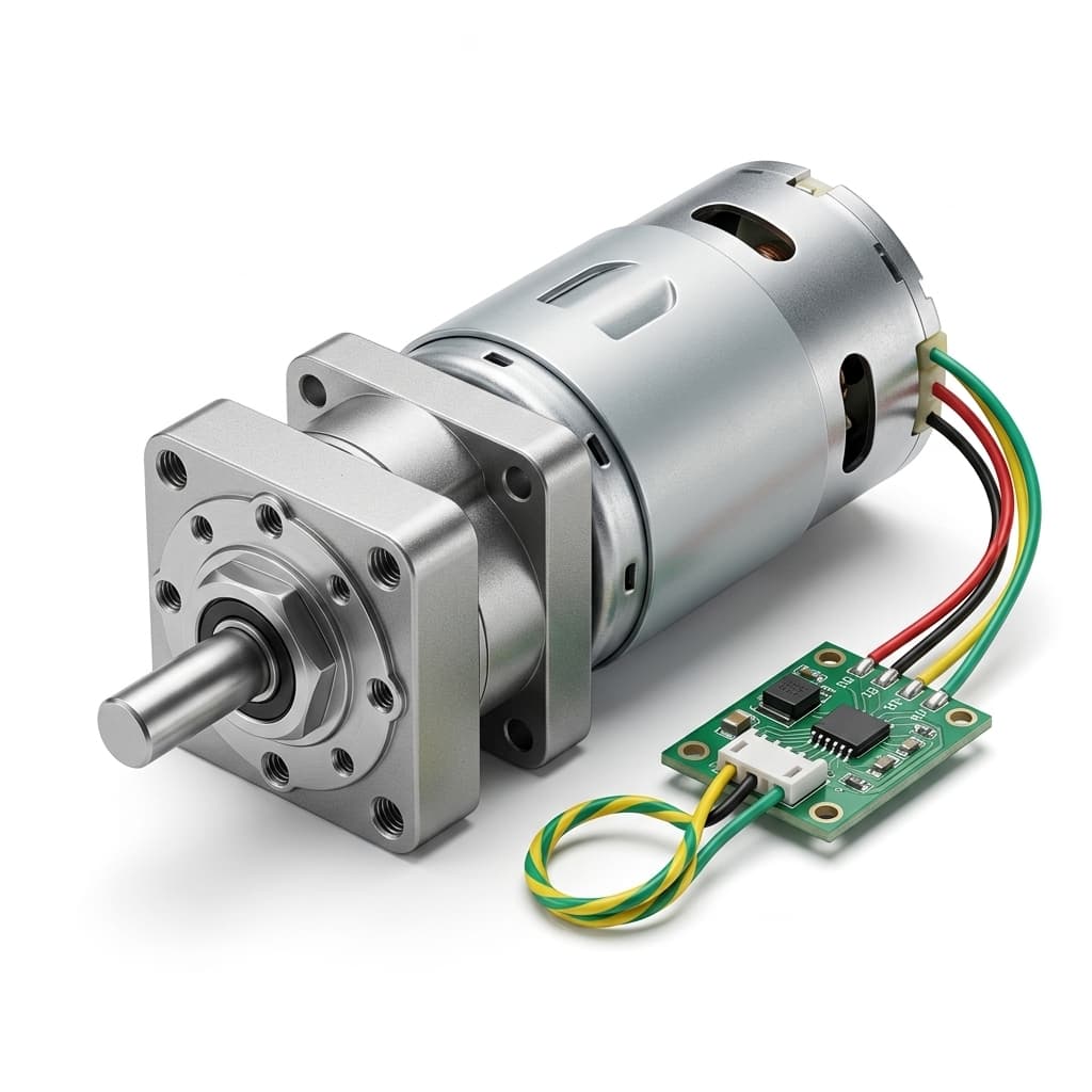
Gear Motor Failure Analysis: Micro-pitting and Tooth Flank Wear in Micro Planetary Gearboxes
Diagnose micro planetary gearbox failures by reading wear patterns, micro-pitting, lubricant breakdown, backlash growth, shaft loads, and validation data before pilot release.
When a micro planetary gearbox fails early in the field, the root cause is often an integration mismatch rather than a single bad gear. The useful question is not just "which tooth broke?" It is "what load path, lubricant condition, duty cycle, and assembly stack-up created the damage pattern?"
This guide is written for OEM engineers reviewing compact gear motors before pilot release. It connects common symptoms such as noise rise, backlash growth, current increase, heat, and tooth flank wear to practical design corrections and validation data.
Fast Triage: Match the Symptom to the Failure Path
Use the first teardown to separate overload, lubrication, material, and alignment problems. A microscope photo and a repeatable bench test are more useful than a generic "failed after N cycles" note.
Noise rises after run-in
Check tooth flank polishing, lubricant migration, bearing ovalization, carrier runout, and gear mesh marks under load.
Backlash grows after life test
Look for tooth flank wear, carrier pin wear, output bearing play, shaft coupling slip, and plastic gear creep at temperature.
Current draw climbs
Review grease thickening, contamination, adhesive wear, misalignment, seal drag, and overload near an end stop.
Teeth show gray frosting or pits
Treat it as a contact fatigue warning: lubricant film may be too thin, surface stress too high, or tooth contact poorly distributed.
1. Output Bearing Overload Starts the Damage Chain
The output shaft of a micro planetary gearbox is supported by a small bearing stack. In standard, cost-optimized gearboxes, this may include sintered bronze sleeve bearings. In higher-load designs, the output stage may need dual ball bearings, a larger shaft, or a reinforced carrier.
If the mechanism pushes a gear, pulley, cam, or lead screw onto the shaft, the gearbox can see axial or radial loads that were never included in the catalog torque rating.
- Typical field symptom: shaft wobble, acoustic noise increase, current rise, output seal wear, uneven tooth contact, or sudden tooth damage after the bearing hole ovalizes.
- Root cause to check: pulley belt tension, overhung load distance, press-fit force during assembly, lead screw thrust, side-loaded drive wheels, or a housing datum that pulls the shaft off-axis.
- Engineering correction: review custom shaft and flange design, bearing type, support spacing, output shaft diameter, and the real radial/axial load direction before sample approval.
[!NOTE] A gear motor can pass a no-load speed test and still fail quickly if the final mechanism side-loads the output shaft. Shaft load belongs in the RFQ, not only in the final assembly drawing.
2. Lubricant Film Collapse Leads to Micro-pitting
Planetary gearboxes are packed with grease chosen for the expected speed, load, temperature, material stack, and duty cycle. When the oil film inside that grease becomes too thin, the tooth flanks no longer separate cleanly. Asperities on opposing gear surfaces begin to contact each other under localized stress.
That condition can create micro-pitting: small contact fatigue marks that often look like gray frosting, dull patches, or fine pits on the active tooth flank. In a micro gearbox, these marks may be tiny, but they are important because they show that the contact stress and lubrication regime are not balanced.
Common reasons the film becomes too thin:
- The application uses a higher continuous load than the sample review assumed.
- Duty cycle changes from intermittent movement to long repeated operation.
- Temperature lowers the effective lubricant viscosity or pushes grease away from the mesh.
- Gear surface roughness, carrier runout, or center distance error concentrates stress on one flank area.
- Contamination turns the grease into a cutting compound.
- A high-ratio gearbox is repeatedly driven into an end stop, creating boundary-lubrication events.
Micro-pitting is not only a cosmetic issue. It can progress into tooth flank wear, noise increase, backlash growth, and eventual tooth fatigue if the stress pattern remains unchanged.
The corrective path is usually not one single part swap. Review the grease type, gear material, surface finish, hardness, stage ratio split, load profile, and thermal path together. If the design is choosing between plastic, MIM, powder metallurgy, brass, or machined steel stages, use the POM vs MIM metal gear material guide as an early screening step.
3. Tooth Flank Wear: Abrasive, Adhesive, and Fatigue Wear
Tooth flank wear is the visible record of how the gear teeth actually contacted each other in the mechanism. Three patterns matter most in compact planetary gearboxes.
Abrasive Wear
Abrasive wear happens when hard particles or rough surfaces remove material from the tooth flank. In a micro gearbox, even small debris from machining, plating, housing wear, or degraded grease can become damaging because the contact area is small.
Look for directional scratches, dull flank bands, or darkened grease. If the wear tracks are concentrated near one edge, also check alignment and carrier runout.
Adhesive Wear and Galling
Adhesive wear happens when the lubricating film breaks down enough for local metal-to-metal contact. Small welded contact points form and tear away. On metal gears, this may appear as smearing, scuffing, or galling. On hybrid gear trains, it may also show as rapid polishing, heat discoloration, or material transfer.
The practical fix is to reduce boundary contact: lower peak load, add current limits, change grease, improve surface finish, change material pairing, or increase frame size.
Tooth Fatigue and Micro-pitting
Micro-pitting sits closer to contact fatigue. Repeated local stress creates fine surface cracks and small pits. If ignored, the local damage can expand into larger flank pitting or tooth-root fatigue.
For early-stage design review, the Archard wear model is useful as a screening mental model:
Wear volume = wear coefficient x normal load x sliding distance / material hardness
It does not replace life testing for a finished drive, but it keeps the right variables visible. If the same compact gearbox carries more load, runs more cycles, or uses a softer material without enough lubrication margin, wear risk rises. If hardness, surface finish, grease, alignment, and load control improve, the risk moves in the right direction.
4. Shock Loads and Back-driving Damage the First Stages
Micro planetary gearboxes are designed to drive loads, not to be driven violently by external loads. If a user forces a smart lock, a valve hits a hard stop, or a robot arm impacts an obstacle, the shock can travel backward through the output stage into the carrier, planet gears, and sun gear.
- Typical field symptom: chipped teeth, sudden backlash increase, cracked plastic first stages, bent carrier pins, or noise immediately after an impact event.
- Root cause to check: manual forcing, unprotected end stops, controller overcurrent, blocked load at startup, shipping damage, or test fixtures that apply step loads unrealistically.
- Engineering correction: review slip clutches, mechanical compliance, controller current limits, end-stop detection, reinforced gear stages, or high torque miniature gear motor options.
For lock actuators and valve actuators, manual back-driving can be more damaging than normal motor torque. A slip clutch, stall-current limit, or reinforced metal gear stage should be reviewed when users can force the mechanism externally.
5. Backlash Growth Is a Failure Indicator, Not Just a Precision Spec
Backlash is usually discussed as a positioning metric, but it is also a useful health indicator. If output backlash grows after a defined life test, something in the gear train or support stack has changed.
Common causes include:
- tooth flank wear after lubricant breakdown;
- carrier pin wear or plastic carrier deformation;
- output bearing wear or sleeve bearing ovalization;
- shaft coupling slip;
- gear bore wear or press-fit movement;
- housing or mounting distortion at temperature.
The first sample review should define both the starting backlash and the allowed backlash after load, temperature, and cycle exposure. For the measurement method, use the backlash measurement guide and record the load condition, direction reversal, measurement angle, and fixture stiffness.
6. Use Vibration Monitoring to Catch Wear Trends Early
Small gearboxes are often too compact for elaborate condition monitoring, but simple vibration monitoring can still help during validation. The goal is not to claim a universal failure threshold. The goal is to compare each sample against a known healthy baseline under the same voltage, load, speed, fixture, and temperature.
Useful signals during a life test:
- vibration RMS trend at the gearbox housing or load fixture;
- gear-mesh frequency components and sidebands when the setup can capture them;
- current ripple and average current under the same load point;
- acoustic noise at a fixed distance;
- output speed stability and temperature rise;
- backlash before, during, and after the test interval.
If vibration, current, and noise rise together, teardown should focus on lubrication, tooth flank wear, bearing load, and carrier alignment. If backlash rises without a matching current increase, check output support, coupling, carrier pins, and material creep.
7. A Practical Teardown Workflow for OEM Sample Failures
When a sample fails, preserve the evidence before cleaning it.
- Photograph the complete motor, gearbox, connector, shaft, and mating mechanism.
- Record the last known voltage, load, speed, duty cycle, ambient temperature, current limit, and failure time.
- Measure no-load current, loaded current, output RPM, noise, temperature, and backlash before teardown if the drive still rotates.
- Open the gearbox and photograph grease distribution before wiping any parts.
- Photograph the sun gear, planet gears, ring gear, carrier pins, output bearing, and shaft under magnification.
- Compare wear on forward-drive and reverse-drive flanks.
- Match the damage pattern to a design correction, then repeat the validation test with only the planned changes.
This process turns the failure into design data. It also prevents the most common mistake: replacing a material or grease without fixing the load path that created the wear.
RFQ Data That Prevents Early Gearbox Failure
Do not send only a drawing and ask for price. For a gearbox that can survive the application, include:
- target output torque, speed, gear ratio, and voltage;
- exact duty cycle, including start-stop frequency and rest time;
- maximum continuous torque and peak or stall torque;
- radial and axial load on the output shaft, including lever arm distance;
- shock load, end-stop, jam, or manual back-driving conditions;
- ambient temperature, enclosure temperature, humidity, and sealing target;
- required gear material preference or constraint;
- noise, vibration, backlash, temperature-rise, and life-test acceptance limits;
- mating housing CAD, shaft drawing, connector requirements, and expected annual volume.
For projects where the gear train is already showing early wear, send teardown photos, grease condition photos, current data, backlash data, and any vibration or acoustic trend data with the RFQ. Submit the context here and include the actual load profile, not only the catalog torque target.
FAQ
Is micro-pitting only a metal gear problem?
Micro-pitting is usually discussed for metal rolling/sliding contacts, but the same design review logic matters in hybrid micro gearboxes. Surface stress, lubrication, roughness, alignment, and load cycle still decide whether the tooth flanks remain stable.
Can a stronger metal gear solve early failure by itself?
Sometimes, but not always. If the root cause is output bearing overload, misalignment, grease migration, or uncontrolled end stops, a stronger gear may simply move the failure to the carrier, bearing, shaft, or motor winding.
Should we specify all-metal gears for every high-torque application?
No. Full metal gears can improve shock and temperature margin, but they usually increase acoustic noise and may need a different grease strategy. Start from load, noise, temperature, duty cycle, and validation requirements, then compare metal gear micro planetary drives with hybrid material options.
What is the best early warning signal during validation?
Use a trend set rather than one signal. Current rise, vibration trend, noise increase, temperature rise, and backlash growth together give a stronger warning than any single measurement.
When should the design move to a larger frame size?
Move up in frame size when the required torque, bearing load, thermal rise, or life target leaves no validation margin in the smaller gearbox. A compact drive is only useful if it survives the real load path.
Author

Categories
More Posts
Understanding and Measuring Backlash in Micro Planetary Gearboxes
A practical engineering guide to backlash, arcminutes, static measurement, dynamic reversal behavior, and RFQ data for low-backlash micro planetary gear motor programs.
How to Choose the Right Micro Planetary Gear Motor for Your Application
A comprehensive buyer-side engineering guide on sizing, torque requirements, gear materials, and selecting the optimal micro planetary gear motor architecture.
How to Calculate Planetary Gear Ratio and Output Torque
A practical engineering guide to calculating planetary gear reduction ratio, output speed, output torque, efficiency losses, stage count, and RFQ data for micro planetary gear motor projects.