
Dynamic Shaft Sealing and IP65 to IP68 Protection in Micro Planetary Gear Motors: Parasitic Drag Torque, Seal Architectures, and Waterproof Actuator Engineering
Specify IP65 to IP68 micro planetary gear motors: compare shaft seals, budget drag torque, assess thermal pumping, and prepare an engineering RFQ checklist.
When specifying a micro planetary gear motor for outdoor sensors, medical surgical tools, agricultural automation, fluidic metering, or submersible robotic joints, engineering teams frequently request IP65, IP67, or IP68 ingress protection. However, transferring standard industrial sealing practices down to sub-32 mm miniature gearmotors introduces a severe electromechanical paradox: parasitic seal drag torque.
Seal drag must be compared with torque at the same shaft. As an illustrative budget, 0.02 N·m of friction consumes 0.4% of a 5 N·m drive, but 25% of an 80 mN·m drive. These are assumed values, not measured motor or seal ratings. If breakaway drag plus the driven load exceeds available starting torque, a miniature coreless or brushless motor may fail to start.
Published and content reviewed: November 02, 2026. Scope: Global OEM sourcing, electromechanical integration, and environmental qualification of 6 mm to 32 mm micro planetary gear motors. This is an analytical selection guide, not a report of physical motor testing or certified product performance. Worked examples use explicitly assumed inputs. Model-specific testing, material compatibility checks, and thermal cycle evaluations are required before production approval.
Selection shortcut: where the motor and gearbox can share an enclosure, prefer sealing the low-speed output shaft to reduce the torque penalty reflected to the motor. Compare PTFE lips, elastomeric lips, and protected labyrinths against measured cold-start drag and the actual exposure. For IP67/IP68 immersion, define pressure, duration, rotation, and temperature conditions; a vent that breathes in air cannot continuously equalize pressure underwater.
A specification stating simply "Motor must be IP67" is incomplete without defining allowable parasitic drag torque, operating temperature boundaries, shaft surface hardness, media compatibility, and acceptance test pressure. Submit your sealing and environmental specifications for engineering review with your mounting envelope and drive requirements.
1. The Physics of Dynamic Rotary Sealing on Micro Shafts
Achieving liquid and dust isolation on a rotating shaft requires controlling a dynamic interface as well as every static joint. IEC 60529 defines enclosure IP classifications. ISO 20653 addresses electrical equipment on road vehicles, including additional K-code tests; name the applicable standard and edition in the RFQ.
IP65 vs. IP67 vs. IP68: IP65 combines dust-tight protection with water-jet resistance; IP67 combines dust-tight protection with a temporary-immersion test, commonly summarized as 1 m for 30 minutes for a small enclosure. IP68 requires agreed immersion conditions more severe than IPX7; state depth, duration, and temperature explicitly. An immersion rating does not establish jet or washdown resistance. None of these labels alone establishes shaft rotation, loaded operation, saltwater life, or sterilization capability. Request the complete assembly test report, including shaft state, connectors, mounting, and acceptance criteria.
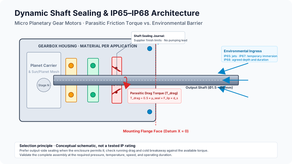
Conceptual output-stage schematic; not to scale and not evidence of a tested IP rating.
Static vs. Dynamic Sealing Boundaries
A sealed micro planetary gear motor contains two completely distinct sealing regimes:
- Static Sealing Boundaries: Interfaces between stationary parts (housing tubes to front mounting flanges, rear motor end-bells to gearbox housings, and lead wire feedthroughs). These are sealed using static elastomer O-rings (typically Shore A 70 NBR or FKM), silicone gaskets, or structural epoxy encapsulation. Static joints present zero parasitic drag during motor rotation.
- Dynamic Sealing Boundaries: The rotating interface where the output shaft emerges from the gearbox housing. Here, the seal must accommodate journal speed, runout, and thermal expansion. A controlled gap alone does not establish immersion protection.
2. Calculating Parasitic Drag Torque and Power Loss
A simple screening model for a cylindrical contact seal is:
T_drag = 0.5 × μ_seal × F_lip × d_shaft
P_drag = T_drag × 2π × n / 60
Use torque in N·m, shaft diameter in meters, rotational speed n in RPM, and power in watts. F_lip is the integrated normal contact load around the lip in newtons, not the net radial force vector, which can cancel around a symmetric ring. The dimensionless friction coefficient μ_seal depends on material, lubrication, temperature, speed, and surface condition. Obtain these inputs from the selected seal supplier or measurements; the equation does not model fluid-film behavior, pressure energization, or viscous losses separately.
Reproducible 3 mm Shaft Example
Assume a lubricated contact coefficient of 0.25, an integrated lip load of 2.0 N, and a 3 mm shaft. For a separate breakaway screening case, assume static friction 0.5 and lip load 5 N. These are hypothetical inputs, not typical FKM ratings:
T_drag      = 0.5 × 0.25 × 2.0 × 0.003
            = 0.000750 N·m = 0.750 mN·m
T_breakaway = 0.5 × 0.50 × 5.0 × 0.003
            = 0.003750 N·m = 3.750 mN·m
P_drag at 100 RPM = 0.000750 × 2π × 100 / 60
                  ≈ 0.00785 W = 7.85 mW
Measure breakaway after a defined stationary dwell and running drag at the required speed, temperature, and wet/dry condition. A small steady loss does not rule out a starting-current problem.
Why Motor-Side vs. Gearbox-Side Sealing Matters
Assume an available motor torque of 0.8 mN·m at the operating point, a reduction ratio N = 64, and overall gearbox efficiency η_total = 0.73. If efficiency is specified per stage, multiply the stage efficiencies first. Rated continuous torque and stall torque are separate limits; stall torque is not continuously available.
T_output_before_seal = T_motor × N × η_total
                     = 0.8 × 64 × 0.73 = 37.376 mN·m
T_output_after_seal  = 37.376 - 0.750 = 36.626 mN·m
Running seal share  = 0.750 / 37.376 × 100 ≈ 2.0%
Breakaway share     = 3.750 / 37.376 × 100 ≈ 10.0%
The example leaves a nominal 33.626 mN·m after the assumed breakaway drag, before load and acceleration demands. It does not prove reliable starting: use the motor/controller starting-current limit, gearbox breakaway loss, cold grease, load torque, and gearhead mechanical rating for that check. At the motor shaft, the assumed 3.750 mN·m seal breakaway demand already exceeds the 0.8 mN·m torque budget.
Prefer an output-side seal where the enclosure layout permits it. Separate cavities or exposed input shafts can require other arrangements; validate their speed and torque budget explicitly. For preliminary sizing, use the gear ratio and output torque calculator, then subtract seal losses and check the supplier's gearbox rating.
3. Rotary Shaft Sealing Architectures: Technical Trade-off Matrix
Use this matrix to shortlist designs, then ask for configuration-specific data. A seal type has no standalone IP rating. The complete motor, gearbox, cable exit, and connectors must be tested together. No universal drag, speed limit, or BOM multiplier is claimed here.
| Sealing architecture | Exposure to investigate | Drag and starting concern | Mechanical constraint | Evidence required before selection |
|---|---|---|---|---|
| Garter-spring elastomeric lip (NBR / FKM) | Splash or immersion with a suitable pressure-oriented design | Contact preload, grease, and cold stiffness affect drag | Journal finish, wear resistance, runout, and lip orientation | Torque vs. speed/temperature; pressure and media limits; complete-assembly ingress test |
| Springless machined PTFE lip | Low-drag rotary sealing where the specific geometry is suitable | Can reduce contact friction; low breakaway is not guaranteed | Installation damage, creep, shaft finish, and reverse pressure | Supplier fit/finish specification and measured dwell-to-start torque |
| Axial V-ring face seal | External splash or particle deflection, often as a secondary barrier | Contact drag changes with axial setting and speed | Counterface and axial space; not a standalone immersion barrier | Installed interference, counterface condition, and relevant spray test |
| Dynamic O-ring with grease cavity | Specialized slow or intermittent rotary applications | Squeeze, dwell, and lubrication can create substantial stiction | Heat, wear, and compound compatibility need explicit approval | Rotary-duty supplier approval plus temperature, torque, and endurance tests |
| Non-contact labyrinth / slinger | Deflection and drainage where immersion is not required | No rubbing lip, but grease shear and cold breakaway can remain | Clearance, orientation, drainage, contamination, and grease retention | Complete-assembly jet/dust tests; no inferred IP65 or immersion rating |
| Ferrofluidic / magnetic liquid seal | Specialist pressure barriers with a compatible fluid system | Viscous loss depends on fluid, gap, speed, and temperature | Water/media compatibility, pressure capacity, packaging, and magnetic circuit | Supplier approval for the actual liquid and differential pressure; life and ingress tests |
Engineering Guidance on Architecture Selection
- Battery-powered locks, pipettes, and portable pumps: Compare PTFE and low-preload elastomeric candidates using cold breakaway and running-current measurements. A material name alone cannot establish battery life or startup reliability.
- Washdown equipment and agricultural robotics: Consider an external slinger or V-ring to protect a primary lip. Specify jet direction, temperature, cleaning chemicals, and the relevant IEC or automotive K-code test; immersion evidence alone is insufficient.
- Submersible mechanisms: Specify external pressure, rotation, mission duration, and pressure cycling. Opposed lips or a pressure-balanced barrier may be candidates, subject to validation. Do not assume that a magnetic liquid seal designed for gas or vacuum is suitable for water immersion.
4. Micro Planetary Motor Torque Budget: Six Screening Scenarios
Frame diameter and gear ratio do not establish an output torque rating. Use the selected motor's thermal rating and the gearhead's mechanical limit, and check whether the quoted assembly torque already includes its seals to avoid subtracting the same loss twice.
The following hypothetical sensitivity cases vary torque and seal drag independently. They are not catalogue ratings or predictions for a frame size. Each percentage is seal drag / available output torque × 100.
| Screening case | Available output torque before seal (mN·m) | Assumed running seal drag (mN·m) | Running budget consumed | Torque remaining before load/acceleration (mN·m) | Decision prompted |
|---|---|---|---|---|---|
| A | 5 | 0.75 | 15.0% | 4.25 | Investigate a lower-preload design or greater torque capacity |
| B | 10 | 0.75 | 7.5% | 9.25 | Check cold-start drag separately |
| C | 20 | 0.75 | 3.75% | 19.25 | Compare remaining budget with driven load |
| D | 40 | 0.75 | 1.875% | 39.25 | Verify gearbox and thermal limits still govern |
| E | 40 | 3.00 | 7.5% | 37.00 | Compare a higher-drag seal under the same load |
| F | 80 | 3.00 | 3.75% | 77.00 | Check speed, heat, and life despite a smaller percentage |
Set a project-specific reserve for load uncertainty, acceleration, aging, temperature, and production variation. A universal torque safety factor cannot replace those inputs. Request a shaft and flange review with the selected seal envelope and torque budget.
5. Output Shaft Journal Tribology & Grinding Specifications
A dynamic lip runs against the shaft journal through a changing lubrication regime. Surface texture, machining lead, and eccentricity can affect leakage and wear. ISO 6194-1:2007 addresses nominal dimensions and tolerances for low-pressure elastomeric rotary lip seals; its catalogue abstract does not establish universal friction coefficients, service life, or all the finish limits below.
Use the selected seal manufacturer's application drawing to agree on these six journal parameters. Do not apply one roughness or hardness value to every elastomer, PTFE lip, shaft material, and shaft diameter.
| Shaft parameter | What to put on the drawing / RFQ | Why it affects selection | Verification record |
|---|---|---|---|
| Surface roughness (Ra) | Supplier-approved range and measurement direction, rather than only a maximum | Excess roughness can abrade the lip; an unsuitable smooth surface can alter lubrication | Profilometer trace at the seal track |
| Roughness depth (Rz) | Agreed Rz limit and surface measurement standard | Ra alone can hide peaks, valleys, and scratches | Surface trace and inspection method |
| Machining lead | No detrimental pumping lead; define finishing and inspection method | Spiral marks can transport fluid depending on rotation direction | Lead inspection and bidirectional leakage test |
| Surface hardness / coating | Compatible material, hardness method, coating thickness, and corrosion resistance | Wear and corrosion can damage the seal track; hardness scales are not interchangeable | Material certificate and surface inspection |
| Dynamic runout / eccentricity | Supplier-approved limits at the seal position, speed, and bearing arrangement | The lip must follow actual journal motion without losing contact | Runout measurement under representative support and load |
| Entry chamfer and edges | Supplier-approved lead-in, radii, and installation sleeve over sharp features | Burrs, grooves, and assembly edges can cut or distort the lip | Drawing review and assembly inspection |
6. Thermal Pumping: Pressure During Hot-to-Cold Immersion
Thermal cycling can increase the pressure differential across a seal. The result depends on whether the cavity remained sealed or leaked while hot. These are analytical scenarios, not observed failure records.
Assume fixed cavity volume, ideal-gas behavior, uniform gas temperature, and initial pressure 101.325 kPa absolute at 25°C (298.15 K). Heating to 65°C (338.15 K) gives:
P_hot = 101.325 × 338.15 / 298.15 ≈ 114.92 kPa absolute
ΔP_hot ≈ +13.59 kPa relative to ambient
Case A: the hot cavity vents to ambient and then becomes sealed before cooling. Cooling from 65°C to 10°C (283.15 K) gives:
P_internal = 101.325 × 283.15 / 338.15 ≈ 84.84 kPa absolute
Ambient-to-cavity difference ≈ 16.48 kPa
At 1 m fresh-water depth: ΔP_ingress ≈ 16.48 + 9.81 = 26.29 kPa
Case B: no gas escapes throughout the entire heat/cool cycle. The final pressure instead follows the original 25°C state:
P_internal = 101.325 × 283.15 / 298.15 ≈ 96.23 kPa absolute
At 1 m fresh-water depth: ΔP_ingress ≈ 5.10 + 9.81 = 14.91 kPa
The hot venting assumption therefore changes the result substantially. These pressure differences do not predict leakage by themselves; lip direction, pressure rating, defects, and cable paths decide whether water enters.
Mitigation Strategies and Limits
- Hydrophobic vent membranes: A dry, air-exposed vent can relieve pressure at its specified airflow rate. Once submerged, it cannot freely draw replacement air from the water. Select water-entry pressure, chemical resistance, orientation, and contamination limits for the actual exposure; do not assume zero differential pressure or a universal breakthrough pressure.
- Potting selected stationary cavities: Potting can reduce trapped gas quantity and protect electronics, but at fixed gas mass and volume the fractional pressure change remains governed by temperature. Do not pot moving parts or infer that a smaller air volume eliminates thermal pressure.
- Opposed lips or pressure compensation: Check external and reverse-pressure capability with the seal supplier. Continuously submerged designs may need a separate pressure-compensation system; test pressure cycling, shaft rotation, temperature transitions, and aging on the final assembly.
7. Electrical Feedthroughs: Preventing Capillary Wire Wicking
The electrical lead wire entry is another potential ingress path. A shaft seal cannot compensate for an unsealed cable, connector, or housing joint. No failure-rate distribution is claimed here.
Standard motor lead wires use flexible stranded copper conductors insulated with PVC, silicone, or PTFE. The microscopic spaces between individual copper wire strands act as high-efficiency capillary tubes.
If moisture contacts the bare stripped wire ends or a non-waterproof external connector, capillary action—assisted by internal thermal vacuum pumping—draws liquid water directly through the inside of the wire insulation, transporting water straight into the motor windings and encoder circuitry.
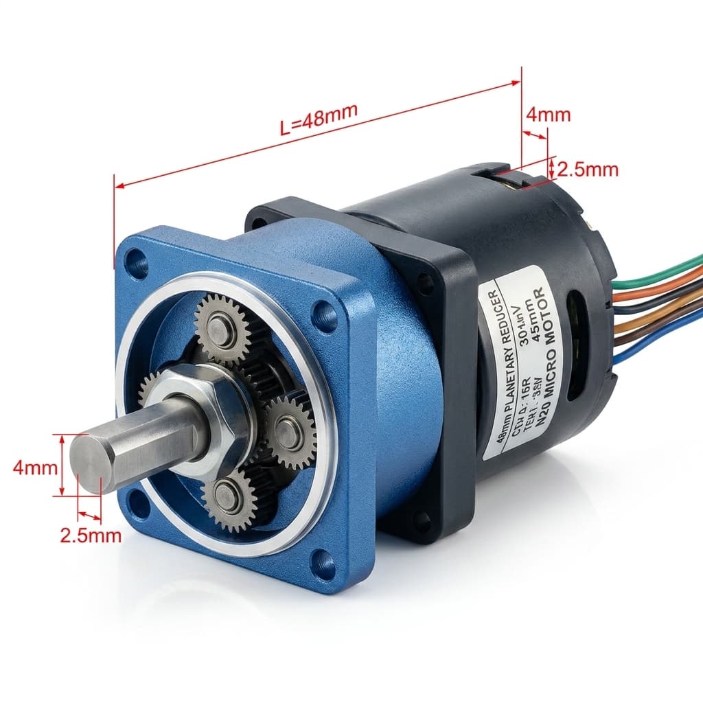
Product illustration for packaging context; the image does not establish an IP rating or show a qualified sealing construction.
Design Protocol for Waterproof Cable Feedthroughs
- Compatible back-potting: Evaluate resin adhesion to the actual insulation and housing, cure shrinkage, thermal expansion, and penetration around conductors. Vacuum degassing alone does not prove a water block; qualify the cured feedthrough by sectioning samples and testing.
- Overmolded strain reliefs: Verify adhesion, cable pull resistance, and thermal-cycle durability. An overmold can still leak along a poorly bonded interface.
- Water-blocked conductors and connectors: Select a cable and connector system approved for the media, depth, temperature, and lifetime. Test the complete harness, including exposed wire ends and mated connectors.
8. Sizing and Selection Engineering Checklist (16-Point RFQ Protocol)
Before issuing an RFQ or approving a tooling drawing, define the following. The acceptance limits belong to the selected assembly and application, not to a generic motor diameter.
Phase 1: Operating Profile & Environmental Envelope
- Target ingress rating: State standard, edition, and rating. Distinguish IEC jet/immersion tests from ISO 20653 automotive K-code washdown tests.
- Working media: Identify fresh water, saltwater, saline solution, alcohol, detergent, oil, and exposure concentration; an IP test is not a chemical-compatibility test.
- Operating temperature: Specify cold-start, running, storage, and fluid temperatures, plus transition rates.
- Depth, duration, and shaft state: Define immersion pressure, mission duration, rotation speed, driven load, and whether the rated assembly was tested while rotating.
Phase 2: Torque Budget & Seal Friction Allocation
- Motor torque limits: Record rated continuous torque, permitted transient torque, controller current limit, and cold starting capability separately from stall torque.
- Gearbox ratio and efficiency: Use overall efficiency at the required operating point and respect the gearhead mechanical rating.
- Seal losses: Set maximum running drag and breakaway torque after a defined dwell, at the hot/cold and wet/dry extremes; identify whether supplied assembly ratings already include them.
- Seal architecture: Compare candidate designs using torque measurements, pressure direction, media compatibility, and available package space.
Phase 3: Shaft Tribology & Mechanical Boundary
- Journal diameter and fit: Agree on numerical limits with the seal supplier; verify that any ISO tolerance designation matches those limits.
- Journal texture and lead: Specify supplier-approved Ra/Rz ranges, finishing direction, and a method to detect pumping lead.
- Material and wear resistance: Define corrosion resistance, hardness measurement, coating compatibility, and inspection location.
- Runout: Define dynamic runout at the seal track with representative bearings, shaft load, and speed.
Phase 4: Enclosure Integrity & Acceptance Testing
- Static joints: Approve O-ring squeeze, gland fill, thermal expansion, and material compatibility for the actual housing tolerances.
- Cable entry: Qualify the feedthrough, conductor water block, strain relief, and mated connector as an assembly.
- Thermal pressure: Identify whether hot venting is possible, the submerged pressure differential, and the limitations of any membrane vent.
- Acceptance protocol: Define qualification samples, test sequence, rotating/stationary state, torque/current limits, and post-test functionality. For production air-decay screening, agree on fixture volume, pressure, stabilization time, test duration, calibrated leak standard, and a reject threshold correlated with water testing of representative good and defective assemblies.
9. Frequently Asked Questions (FAQ)
Q1: Can I make an existing micro planetary motor IP67 by slipping an external O-ring over the shaft?
No rating follows from adding an O-ring alone. Dynamic O-rings can work in supplier-approved rotary applications, but uncontrolled squeeze, lubrication, and dwell can cause excessive drag and wear. Assess a purpose-designed rotary seal, housing joints, and cable entry, then test the final assembly. Do not infer starting torque or service life from the O-ring diameter.
Q2: Why can an IP65 motor pass a water-jet test but suffer condensation in humid conditions?
A water-jet test does not qualify humidity resistance or temperature cycling. Humid air trapped during assembly, permeation, or leakage can lead to condensation when internal surfaces cool below the dew point. A dry vent may help pressure equalization but also passes water vapor; it does not guarantee a dry enclosure. Evaluate assembly humidity, coatings, vent behavior, and temperature-cycle testing together.
Q3: How much does -20°C increase dynamic seal drag torque?
There is no universal multiplier. Compound formulation, lubricant viscosity, dwell, interference, speed, and pressure determine the change. Request breakaway and running measurements at the application's minimum temperature. Compare low-temperature elastomers or PTFE designs only within their supplier-approved limits; the material family name alone does not establish cold-start performance.
Q4: Does IP68 qualify a micro gear motor for autoclave sterilization?
No. IP68 describes agreed immersion conditions, not steam sterilization, vacuum pulsing, chemical resistance, or repeated sterilization life. Specify the sterilization cycle separately and validate all seals, plastics, lubricant, cable materials, electronics, and joints. No single material combination guarantees autoclave suitability.
Q5: Can IP65 protection be achieved without a rubbing shaft seal?
A protected labyrinth or slinger may be a candidate for a tested assembly. Drainage, orientation, clearances, jet direction, and contamination matter, so geometry alone cannot establish IP65. A grease-filled labyrinth can still have viscous drag and cold breakaway resistance. Do not infer immersion protection or zero starting loss from the absence of a rubbing lip.
Q6: Can factory air-decay testing replace IP67 immersion qualification?
No. Air-decay screening can detect production variation after its limits have been correlated with the relevant water test on the actual assembly. Gas leakage and liquid ingress differ with wetting, leak geometry, temperature, volume, and seal pressure direction. An outward-pressure test may miss an external-pressure lip failure. There is no universal pressure, leak-rate threshold, or guaranteed correlation with IP67. Retain assembly qualification and periodic water-test sampling in the agreed control plan.
10. Sources, Standards, and Evidence Boundaries
- ISO — ISO 6194-1:2007, Rotary shaft lip-type seals incorporating elastomeric sealing elements — Part 1: Nominal dimensions and tolerances. Supports dimensional selection for low-pressure elastomeric lip seals. It does not establish the hypothetical torque values used here or certify an assembled motor.
- IEC — IEC 60529:1989+AMD1:1999+AMD2:2013 CSV, Degrees of protection provided by enclosures (IP Code). Defines enclosure protection classifications and associated test requirements. Specify the test edition and final assembly configuration in the purchasing agreement.
- ISO — ISO 20653:2023, Road vehicles — Degrees of protection (IP code). Applies to electrical equipment on road vehicles, including additional K-code requirements. It is a separate application standard, not a blanket certification for every industrial or medical actuator.
Evidence note, November 02, 2026: Public catalogue descriptions establish the identity and scope of these standards; they are not full-text clause verification. The worked torque and ideal-gas examples are reproducible calculations with stated assumptions, not physical test data, supplier guarantees, or customer case studies. Architecture guidance and RFQ questions are a selection framework. Obtain the applicable standard text, supplier drawings, and model-specific test reports before approval.
Technical Support & Custom Sealed Motor Engineering
Engineering a waterproof actuator, submersible mechanism, or outdoor robotic drive? Submit your application requirements, mechanical envelope, target IP rating, and operating duty cycle to our engineering group:
- Request custom shaft and flange configurations with precision plunge-ground seal journals.
- Request CAD and 3D STEP models to evaluate seal packaging and bearing spans.
- Use our gear ratio and output torque calculator to determine torque margins across reduction stages.
- Review the miniature planetary gearboxes product family to discuss frame size and ratio options; request sealing feasibility separately.
- Contact our engineering application team for an environmental sealing review, parasitic drag allocation, and prototype quotation.
Author

Categories
More Posts
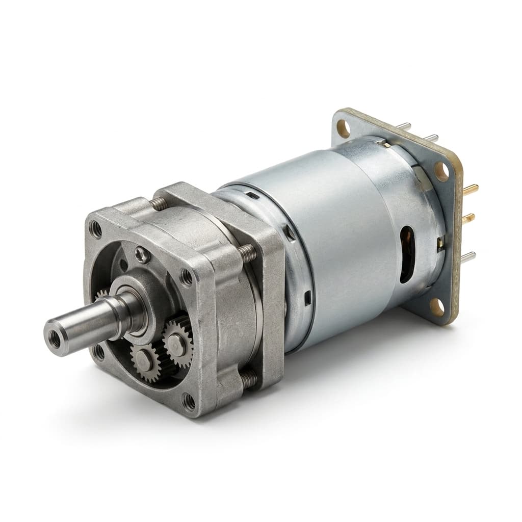
How to Calculate Planetary Gear Ratio and Output Torque
A practical engineering guide to calculating planetary gear reduction ratio, output speed, output torque, efficiency losses, stage count, and RFQ data for micro planetary gear motor projects.
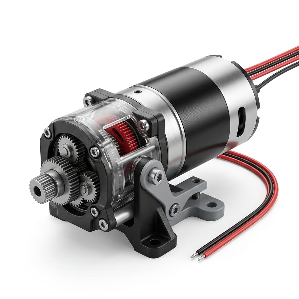
How to Choose the Right Micro Planetary Gear Motor for Your Application
A comprehensive buyer-side engineering guide on sizing, torque requirements, gear materials, and selecting the optimal micro planetary gear motor architecture.
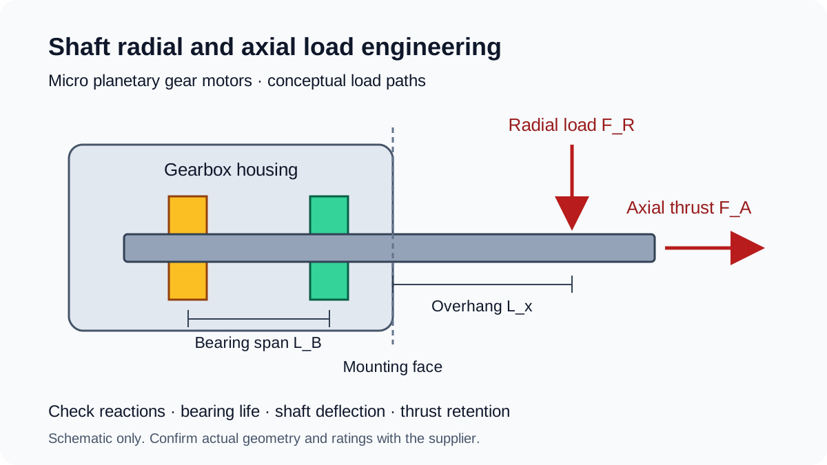
Shaft Radial and Axial Load Engineering in Micro Planetary Gear Motors: Overhung Sizing, Bushings vs. Dual Ball Bearings, and ISO 281 L10h Life
Size micro planetary gear motor shaft loads: calculate overhung reactions, compare bushings and ball bearings, and prepare an RFQ with ISO 281 L10h life inputs.