
Shaft Radial and Axial Load Engineering in Micro Planetary Gear Motors: Overhung Sizing, Bushings vs. Dual Ball Bearings, and ISO 281 L10h Life
Size micro planetary gear motor shaft loads: calculate overhung reactions, compare bushings and ball bearings, and prepare an RFQ with ISO 281 L10h life inputs.
When sizing a micro planetary gear motor, check shaft radial and axial load as well as output torque and RPM. A pulley, pinion, or roller can overload the output support even when transmitted torque is within the motor rating. Overhung load creates a bearing reaction larger than the external force; axial thrust also depends on how the shaft and bearing rings are retained.
Published and content reviewed: October 29, 2026. Scope: Global OEM sourcing and engineering screening of 6 mm to 32 mm micro planetary gear motors. The calculations below use explicitly stated, hypothetical inputs. They are reproducible screening examples, not measured product data, certified load ratings, or a prediction of complete gearmotor service life. Obtain model-specific drawings, bearing data, and a validation plan before approving a design.
Selection shortcut: start with actual belt tensions or gear forces, calculate reactions at the real load distance, then check bearing fatigue, static overload, shaft deflection, retention, and gearbox limits separately. Bushings require material-specific pressure, speed, and PV checks; dual ball bearings do not create a universal load rating.
A specification such as "Max Radial Load: 10 N" is incomplete without load distance, speed, duty, and life conditions. Submit your shaft loading requirements for engineering review with your mounting envelope and mechanism drawing.
1. Mechanics of Overhung Radial Load: The Cantilever Lever Arm
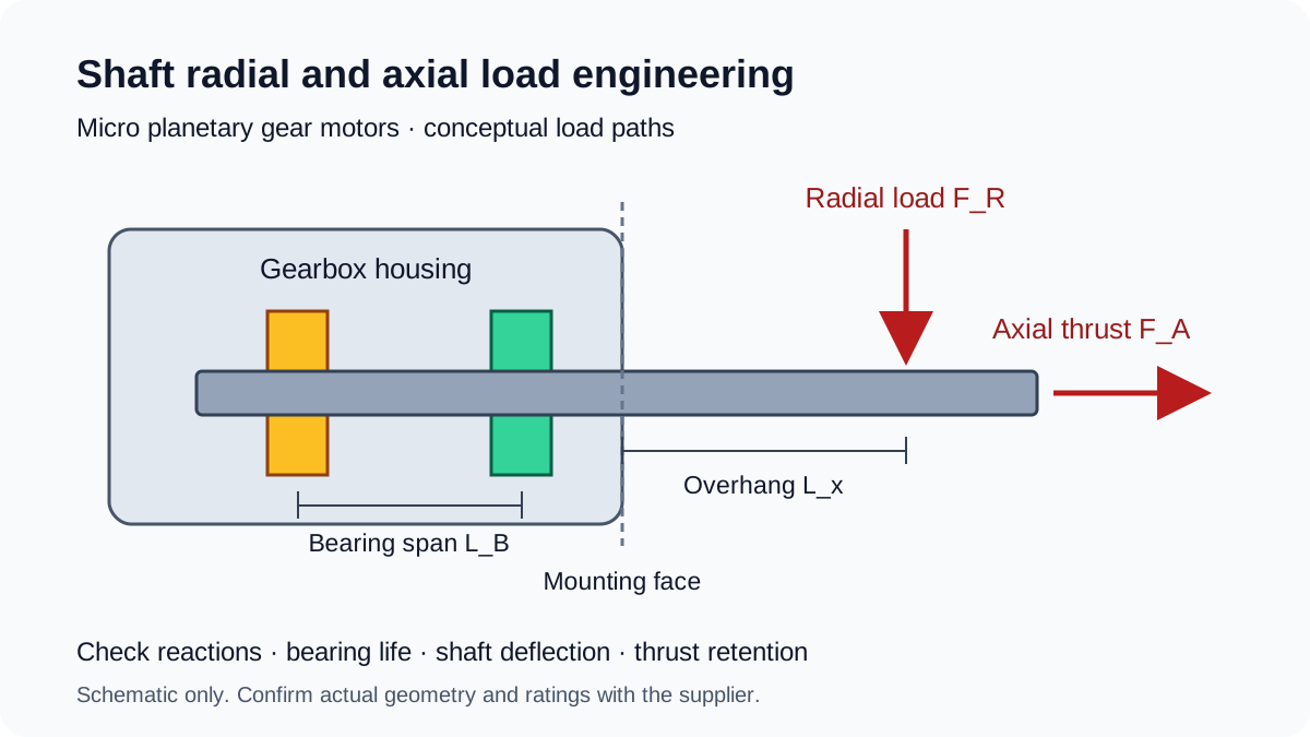
A timing belt pulley, spur pinion, friction roller, or cable capstan applies force perpendicular to the shaft. The distance between that force and the output supports creates a bending moment. The diagram shows an idealized two-support shaft; actual bearing positions must come from the supplier drawing.
Calculate Transmission Force Before Choosing a Drive Factor
Torque and pitch diameter give tangential force, not necessarily total shaft radial load:
F_t = 2000 × T_2 / d_pHere F_t is tangential force in N, T_2 is operating torque in N·m, and d_p is pitch diameter in mm. Use the working pitch diameter for the actual gear geometry; KHK's gear dimension reference distinguishes reference and working dimensions.
- Spur gear: at working pressure angle
alpha, the separating component isF_t × tan(alpha)and the resultant transverse shaft load isF_t / cos(alpha), ignoring friction. At 20°, the resultant is approximately1.064 × F_t. - Timing belt: torque sets the tight/slack tension difference, while bearing load comes from the vector sum of both belt tensions. With nearly parallel spans it is approximately their sum. Pretension can create substantial radial load even at zero transmitted torque.
- Helical gear: calculate tangential, separating, and axial components using the actual working pressure and helix angles. A single radial multiplier omits axial thrust.
- Friction roller or wheel: include normal contact force, supported weight, shock, and drive force in the load vector.
A supplier drive factor may be used for preliminary screening only when its tension and geometry assumptions match the application. Do not use generic belt multipliers in place of known pretension.
Derate Permissible Radial Load with Distance
For two ideal radial supports and one overhung force, moment equilibrium gives reaction magnitudes:
R_1 = F_R × (L_B + c + L_x) / L_B
R_2 = F_R × (c + L_x) / L_BF_R: applied external radial force, N.L_B: front-to-rear bearing center span, mm.c: distance from front bearing center to mounting face, mm; positive when the bearing is behind the face.L_x: mounting face to load center distance, mm.R_1: front reaction, opposing the applied load;R_2: rear reaction, acting in the same direction as the applied load in this model.
Worked geometry example: with L_B = 4 mm, c = 1.5 mm, L_x = 6.5 mm, and F_R = 12 N, the front reaction is 36 N and rear reaction is 24 N. The net support force is 36 − 24 = 12 N, as required by equilibrium. Internal gear forces, preload, and other external loads must be added for an actual assembly.
If front-bearing reaction alone limits an existing rating, a conditional distance correction is:
F_R,perm(L_x) = F_R,0 × (L_B + c + L_x,0) / (L_B + c + L_x)Using the same span and offset, moving the load from 3 mm to 9 mm gives 8.5 / 14.5 = 0.586, or a 41.4% reduction in allowable external force. This correction does not approve shaft bending, housing stiffness, retention, or gear contact; ask the supplier which constraint controls its rating.
2. Internal Cross-Talk: Shaft Tilt and the Planetary Stage
In designs where the output shaft is integral with the final planet carrier, shaft or housing deflection can tilt the carrier and shift tooth contact toward an edge. Other architectures support the carrier separately, so the load path must be checked on the actual cross-section.
Establish an Application-Specific Tilt Limit
There is no universal 3-arcminute acceptance limit for every micro planetary gearbox. Permissible misalignment depends on gear face width, tooth geometry and modifications, material, carrier stiffness, bearing span, fits, and operating load. A diagram cannot establish contact stress or time to failure.
For a separate idealized fixed cantilever with a point force at distance a from the fixed section:
I = π × d^4 / 64
Tip deflection delta = F_R × a^3 / (3 × E × I)
Tip slope theta = F_R × a^2 / (2 × E × I)
Use N and mm throughout, with E in N/mm² (about 205,000 N/mm² for an illustrative steel shaft); slope is in radians. These expressions are not the two-bearing carrier model above. D-flats, grooves, stepped sections, support compliance, and bearing clearance require a more complete calculation or FEA. Request loaded shaft displacement and gear-contact evidence where alignment is critical.
3. Bearing Architecture Comparison: Bushings vs. Ball Bearings
Compare support arrangements using the required load path and evidence. Architecture alone does not establish a force, RPM, noise, cost, or life rating.
| Bearing architecture | Selection benefit | Important boundary | Evidence to request |
|---|---|---|---|
| Single sintered bronze bushing | Compact support for modest, validated duty | Short support length can increase pressure and tilt; thrust needs its own surface | Material, lubricant, pressure/speed/PV limits, clearance, wear test |
| Dual sintered bronze bushings | Support spacing can improve shaft guidance | Wear, housing alignment, and lubrication still control performance | Span, fits, reactions at both sleeves, loaded wear results |
| Front ball bearing + rear bushing | Rolling support at the output with a compact rear support | Ball-bearing fatigue and sleeve wear need separate checks | Exact bearing data plus rear-bushing pressure and wear limits |
| Dual deep-groove ball bearings | Defined support span and bearing fatigue calculation | Axial load sharing depends on locating/floating arrangement and fits | Cross-section, C/C_0 ratings, equivalent loads, retention limits |
| Dual ball bearings with spring preload | Controlled preload can reduce play and improve stiffness | Extra preload increases friction, heat, and equivalent load; zero play is not guaranteed | Spring force over travel/temperature, preload scheme, loaded endplay |
| Angular-contact bearing arrangement | Can provide a defined thrust load path | Direction, pairing, contact angle, and preload determine capability | Bearing orientation, axial reactions, retention and thermal checks |
| External supported shaft with coupling | Can route pulley or wheel loads into an external housing | Isolation depends on coupling compliance and alignment; avoid overconstraint | System drawing, external bearing calculation, coupling forces |
If packaging forces the pulley far outside the flange, compare a shorter overhang or an external supported shaft before increasing the gearmotor frame size. Request a CAD/STEP envelope to establish bearing span and interface datums before freezing the mechanism.
4. Sintered Bronze Bushing Boundaries: Pressure, Speed, and PV
Oil-impregnated sintered bushings need material- and lubricant-specific operating limits. They may run in boundary, mixed, or hydrodynamic lubrication depending on conditions. Low speed, frequent starts, heat, and contamination matter; ISO 281 rolling-bearing fatigue life does not apply to a sleeve bushing.
Calculate Projected Pressure and Sliding Speed
For a preliminary projected-area check:
P_b = R / (d_shaft × L_bushing)             [N/mm² = MPa]
V = π × d_shaft × n_out / 60000            [m/s]
PV = P_b × V                              [MPa·m/s]
Use the reaction R at the bushing, journal diameter and effective sleeve length in mm, and output speed in RPM. Check pressure, speed, and PV individually against the selected material's published limits and temperature/lubrication conditions. A passing PV product cannot override an excessive pressure or speed. This simplified pressure is an average; misalignment can produce higher local edge pressure.
Reproducible Bushing Screening Example
Assume d = 3 mm, sleeve length L = 3 mm, n_out = 300 RPM, F_R = 12 N, L_x = 6 mm, L_B = 4 mm, and c = 1.5 mm:
- Front reaction:
R_1 = 12 × (4 + 1.5 + 6) / 4 = 34.5 N. - Projected pressure:
P_b = 34.5 / (3 × 3) = 3.83 MPa. - Sliding speed:
V = π × 3 × 300 / 60000 = 0.0471 m/s. - PV product:
3.83 × 0.0471 ≈ 0.181 MPa·m/s.
Decision: these are required operating values to compare with a supplier material datasheet, not evidence that a specific bushing passes or fails. No material limits or wear test are supplied in this example, so it cannot predict seizure, bore growth, or hours of service. If the supplier cannot document suitable limits and a wear test, keep qualification open or evaluate rolling bearings/external support.
5. Sizing Dual Ball Bearings: ISO 281 L10h Calculation Protocol
Basic rating life L10h is the calculated operating time that 90% of a population of apparently identical bearings is expected to reach or exceed under the defined conditions. It concerns rolling-contact fatigue, not a guaranteed gearmotor lifetime. See SKF's rating-life selection guide for the manufacturer calculation framework.
For constant equivalent load and speed:
L10h = (10^6 / (60 × n_out)) × (C / P_dyn)^pC: the specific bearing's basic dynamic load rating, N.P_dyn: equivalent dynamic load at that bearing, N.n_out: that bearing's rotational speed, RPM.p = 3for ball bearings;p = 10/3for roller bearings.
Calculate both bearings using their own reactions and data. Do not add two catalogue C ratings or assume that two bearings share an overhung force equally. The assembly's reliability also cannot be inferred simply from the better individual L10h value.
Combined Radial and Axial Load
Use the selected bearing manufacturer's load-factor table and the actual axial locating arrangement:
P_dyn = X × F_r,bearing + Y × F_a,bearingThe threshold e and factors X and Y depend on bearing type, internal geometry, clearance, and load ratio; some deep-groove cases reduce to P_dyn = F_r,bearing. Do not assume a universal threshold or divide external thrust equally between two bearings. Include preload and internal gear forces where applicable. Modified life calculations additionally require lubrication, contamination, reliability, and operating-condition inputs.
Worked fatigue example, hypothetical inputs: C = 100 N, front reaction P_dyn = 30 N, purely radial loading, no preload, and n_out = 150 RPM give:
L10h = (1,000,000 / 9,000) × (100 / 30)^3 ≈ 4,115 hoursThe assumed C value is not a catalogue rating for a named motor or bearing. Check lubrication, minimum load, static safety, shaft stress, gearbox wear, motor life, and temperature before interpreting this as a design candidate.
ISO 76 Static Load Safety
ISO 76:2006 defines rolling-bearing static load ratings and static equivalent loads within its stated scope. Use the selected bearing manufacturer's static-load method:
s_0 = C_0 / P_0Here C_0 is basic static load rating and P_0 is static equivalent load, both in N. Agree the required static safety factor for the shock profile, rotation accuracy, noise, and application. ISO 76 does not make a single safety-factor range or a universal allowable press force suitable for every assembly.
For variable duty, evaluate each load/speed segment and fatigue damage using a suitable equivalent-load method. Stopped dwell contributes no revolutions, but still requires static and wear checks; a duty percentage alone is not a permissible-load multiplier.
6. Frame-Size Sizing: 6 mm to 32 mm Qualification Matrix
Housing diameter helps shortlist packaging; it does not determine shaft force capacity. No verified model-specific radial/axial ratings are provided here. Use this matrix to request the missing evidence for the candidate motor rather than treating frame size as a load rating.
| Candidate frame OD | Confirm on the actual drawing | Radial qualification input | Axial/assembly qualification input |
|---|---|---|---|
| 6 mm | Journal diameter, support type, effective sleeve length | Reaction and material wear limits for the actual miniature support | Thrust surface, retention direction, assembly reaction path |
| 10 mm | Bearing or sleeve identity, span, flange datum | C/C_0 or material limits, load distance and speed | Ring location, push/pull limits, fit specification |
| 12 mm | Output shaft section, flats, grooves, bearing positions | Bending stress, support reactions, required fatigue/wear life | Retainer and shoulder capacity, mating hub tolerances |
| 16 mm | Support span, bearing clearance, preload if present | Load spectrum and combined-load calculation | Preload contribution, loaded endplay, assembly tooling |
| 22 mm | Housing support stiffness and gear-to-shaft load path | Shaft displacement, bearing and carrier checks | Axial locating scheme, reverse thrust and shock conditions |
| 28 mm / 32 mm | Wheel/pulley overhang and mounting stiffness | Whole-system loads; evaluate external support where needed | Retention, thrust reversal, fixture and first-article checks |
7. Axial Thrust Dynamics and Assembly Press-Fit Shock
Axial force acts along the shaft centerline. Push and pull limits can differ because shoulders, bearing rings, circlips, adhesives, thrust washers, and housing seats carry load differently.
- Push toward the gearbox: trace the force through shaft shoulders, bearing inner rings, rolling elements or thrust surfaces, outer rings, and housing retention. Confirm whether load can reach the carrier or gear faces.
- Pull away from the gearbox: identify the retaining ring, shaft shoulder, adhesive joint, or other retention feature that closes the load path. Obtain its directional allowable load.
- Alternating thrust: check both directions, seating, endplay changes, and any spring preload over the operating temperature range.
Prevent Assembly Damage with the Correct Reaction Path
Press-fitting a pinion or pulley can impose more axial force than normal operation. Do not use bearing static radial rating C_0 directly as an allowable axial press force. Interference, contact length, finish, material, and tooling determine the assembly demand.
Tooling rule: have the supplier approve a fixture that reacts assembly force directly through the loaded shaft/component, avoiding transfer through the rolling elements or gear train. A rear extension of the output shaft, if accessible and approved for this purpose, may provide a reaction point. A rear extension of the motor rotor shaft is generally separated by the gear stages and must not be assumed to support the output shaft. Supporting only the flange or bearing outer ring also does not by itself bypass the balls.
If a direct support path is unavailable, agree a different hub/shaft fit or assembly method. Record press force versus displacement and check endplay, runout, no-load current, and noise before and after assembly; acceptable values belong on the approved drawing and inspection plan.
8. Engineering Life Sensitivity: L10h vs. Radial Load
The figure shows one normalized mathematical curve, not a measured comparison between bushings and ball bearings. With the same ball bearing, fixed speed, unchanged geometry, and purely radial equivalent load proportional to the applied force, life varies as P_dyn^-3.
Straight segments connect calculated points. The matching values make the figure reproducible:
| Equivalent load / reference load | Relative L10h | Interpretation at unchanged speed and C |
|---|---|---|
| 1.00× | 100.0% | Reference calculation |
| 1.25× | 51.2% | 25% more load nearly halves calculated fatigue life |
| 1.50× | 29.6% | 50% more load leaves about three-tenths of reference life |
| 2.00× | 12.5% | Double load gives one-eighth of reference life |
| 2.50× | 6.4% | Check whether the basic model remains applicable |
| 3.00× | 3.7% | Static and other operating limits still require separate checks |
A dual-bearing support can change reactions and stiffness, but it does not automatically increase C or life. Preload must be included in bearing loading. Bushings have no ISO 281 L10h curve; their wear performance requires material data and application testing.
9. The Shaft Mechanical Load RFQ Engineering Checklist
Before freezing CAD or issuing an RFQ, record the inputs and unresolved limits below.
Phase 1: Mechanism Load Characterization
- Load datum: flange-to-load-center distance, bearing span, and front-bearing offset, all in mm.
- Radial load vector: belt pretension and both span tensions, gear forces, weight, and shock as applicable.
- Operating profile: minimum/nominal/maximum loaded RPM, starts, reversals, dwell, and temperature.
- Axial load: push, pull, or alternating direction, magnitude, duration, and assembly loads.
Phase 2: Bearing and Gearbox Qualification
- Support identity: exact rolling-bearing designation or sleeve material, lubricant, fits, and dimensions.
- Separate limits: bearing fatigue/static checks, sleeve pressure/speed/PV, shaft stress, and housing/gear contact checks.
- Play and alignment: permissible loaded displacement, tilt, endplay, and measurement method agreed for the application.
- Preload and retention: preload range over temperature and a documented directional thrust path.
Phase 3: Shaft Geometry and Fit
- Material and heat treatment: specified with corrosion, wear, and fatigue requirements.
- Shaft features: D-flat, cross-hole, groove, spline, and mating hub geometry included in the stress/fit review.
- Fillets: drawing-specific radii and reliefs reviewed for stress concentration and mating-part clearance.
- Fit stack: shaft and hub tolerances assessed together; shaft tolerance class alone does not establish interference.
Phase 4: Assembly and Quality Verification
- Fixture: output-shaft reaction path approved; no assumption that a motor rear shaft or flange support bypasses the bearings.
- First article: record press force, radial play, endplay, runout datum, no-load current, and noise with agreed test conditions.
- Life test: representative loads, speed, temperature, sample count, duration, and failure criteria agreed; accelerated testing needs a justified acceleration model.
- Release evidence: identify drawing revision, approved motor configuration, signed load limits, and remaining qualification gaps.
Use the gear ratio and output torque calculator for preliminary torque/speed relationships. Obtain loaded performance data for the candidate motor; a calculated ratio does not establish its continuous or peak torque capability.
10. Frequently Asked Questions (FAQ)
Q1: Why do datasheets specify radial load at "5 mm from flange"?
The overhang changes bearing reactions and shaft bending. For L_B = 4 mm and c = 1.5 mm, moving the load from 5 mm to 10 mm changes a front-reaction-limited allowable force by 10.5 / 15.5 = 0.677, a 32.3% reduction. Use the actual geometry and ask which limit controls the rating.
Q2: Is 0.1 degrees of shaft tilt automatically a failure?
No universal angle establishes failure across different gearboxes. It can be significant for a small gear mesh, but permissible tilt depends on gear geometry, stiffness, bearing arrangement, and contact requirements. Request a loaded alignment/contact assessment for the exact design rather than adopting a generic arcminute threshold.
Q3: When can I specify sintered bronze bushings instead of ball bearings?
When the actual support reactions, pressure, speed, PV, temperature, lubrication, and wear-test results meet the required duty and play limits. There is no universal force or RPM cutoff. Ball bearings are a candidate when fatigue calculation and controlled support geometry are needed; external support may be preferable for a heavily loaded pulley.
Q4: Can ball bearings handle press-fitting a gear or pulley?
Only an assembly-specific load-path review can answer that. Avoid transmitting installation force through rolling elements. Use approved direct output-shaft support or another fit/assembly method, and verify the resulting condition. A bearing's static radial C_0 rating is not an allowable axial press force.
Q5: What is the difference between radial play, deflection, and runout?
Radial play is clearance movement measured under specified conditions. Deflection is elastic displacement under load. Runout is indicator variation as the shaft rotates relative to a stated datum and can include geometry, eccentricity, and bearing effects. They are different measurements; do not simply add their catalogue values as one TIR specification.
Q6: Does wave-spring preload always improve bearing life?
No. Proper preload can reduce play and improve stiffness, but adds bearing load, friction, and heat. The useful range depends on bearing design, fits, spring travel, and thermal expansion. Include preload in the equivalent-load calculation and confirm loaded endplay and temperature in testing.
11. Sources, Standards, and Evidence Boundaries
- SKF — Size selection based on rating life. Manufacturer reference for rolling-bearing rating-life selection. Use the current bearing catalogue and calculation method for the exact part; no product C rating is taken from this article's hypothetical examples.
- ISO — ISO 76:2006, Rolling bearings — Static load ratings. Official scope for basic static load ratings and static equivalent loads. The public abstract is not a miniature gearmotor load table or assembly-tooling approval.
- KHK Gears — Calculation of Gear Dimensions. Gear geometry reference, including reference and working pitch dimensions and pressure angles. It does not supply a universal carrier-tilt limit or a bearing-life curve.
Evidence note, October 29, 2026: these references cover calculation methods and component geometry, not measured performance of the motor frames listed here. The arithmetic examples and normalized figure are analytical illustrations. No first-party endurance results, universal bushing material limits, or certified radial/axial capacities are claimed. Ask the supplier for part-specific bearing/material data and assembly validation records.
Technical Support & Custom Shaft Engineering
Preparing a belt drive, pinion interface, or lead screw actuator? Send your drawing revision, load center distance, radial/axial load vectors, loaded RPM, duty cycle, temperature, and life target so engineering can review the candidate support arrangement and identify required qualification evidence.
- Request CAD/STEP files to establish mounting and shaft datums.
- Review custom shaft and flange capabilities for interface options.
- Compare the miniature planetary gearboxes catalog for packaging candidates.
- Contact our engineering application team for a configuration review and prototype quotation. Confirm available documentation, validation scope, and lead time for your project.
Author

Categories
More Posts
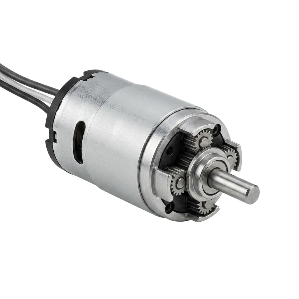
Understanding and Measuring Backlash in Micro Planetary Gearboxes
A practical engineering guide to backlash, arcminutes, static measurement, dynamic reversal behavior, and RFQ data for low-backlash micro planetary gear motor programs.
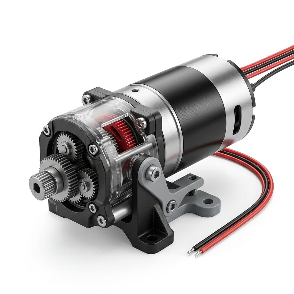
How to Choose the Right Micro Planetary Gear Motor for Your Application
A comprehensive buyer-side engineering guide on sizing, torque requirements, gear materials, and selecting the optimal micro planetary gear motor architecture.
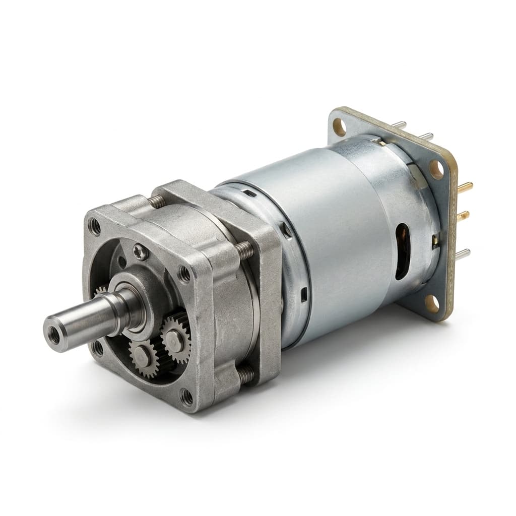
How to Calculate Planetary Gear Ratio and Output Torque
A practical engineering guide to calculating planetary gear reduction ratio, output speed, output torque, efficiency losses, stage count, and RFQ data for micro planetary gear motor projects.