LogoMicro Planetary Motor
Start inquiry
LogoMicro Planetary Motor
WhatsApp
LogoMicro Planetary Motor

China-based industrial OEM supplier supporting customization, quality control, and global delivery.

Inquiry Email

[email protected]

Email app

Include OD/length, voltage, torque, loaded speed, ratio, drawings, quantity, and destination.

Instant Chat

+86 18857971991

Chat on WhatsApp

Fast channel for clarifying specs, drawings, and sample timing.

Products
  • Product Overview
  • Micro DC Planetary Gear Motor
  • Micro BLDC Planetary Gear Motor
  • Encoder Micro Planetary Gear Motor
  • Miniature Planetary Gearboxes
  • Custom OEM Drive Assemblies
  • Coreless Micro Planetary Motors
  • Low Backlash Planetary Motors
  • Low Noise Micro Planetary Motors
  • High Torque Miniature Motors
  • Metal Gear Planetary Drives
Solutions
  • Solutions Overview
  • Robotics & AGV
  • Medical Devices
  • Smart Lock Actuators
  • Valve Actuators
  • Optical Instruments
  • Industrial Automation
OEM Capabilities
  • OEM Overview
  • Custom Engineering
  • Gear Machining
  • Testing & Validation
  • Export & Logistics
Resources
  • CAD / STEP Request
  • Ratio & Torque Calculator
  • POM vs MIM Gear Materials
  • Premium Brand Alternatives
  • Blog
  • About
  • Contact / RFQ
  • Quality & Testing
  • Privacy Policy
  • Cookie Policy
  • Terms of Service
© 2026 Micro Planetary Motor. All Rights Reserved.|Micro Planetary Motor is the micro drive product site operated by Linkup Ai Co., Ltd.; manufacturing programs are coordinated through the Linkup Precision manufacturing network.|Traceable process checks | RoHS, REACH, and applicable CE file support by project scope
← Back to Solutions

Robotics & AGV

High-torque, low-backlash metal planetary gear motors for AGV/AMR drive wheels, service robot joints, robot vacuum chassis lift modules, inspection crawlers, and compact UAV or small robotic actuators.

Target Buyer:For robotics engineers, startups, and system integrators comparing torque density, backlash, shock load, feedback, shaft support, mounting geometry, and battery efficiency before prototype builds.
Discuss on WhatsAppSend RFQEmail specsRequest CAD / STEP

Solution recommendations are confirmed by RFQ after the real load, envelope, quantity, and validation scope are reviewed.

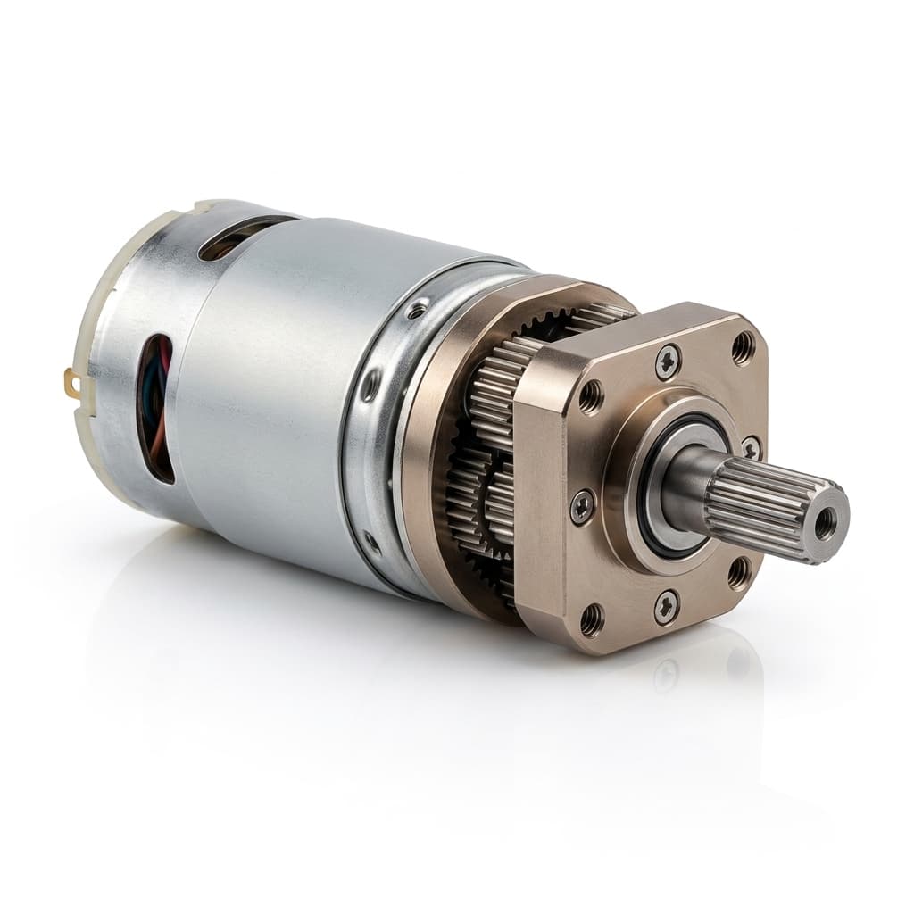
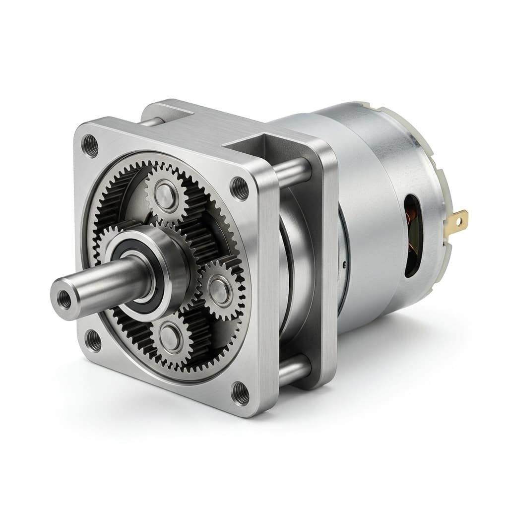
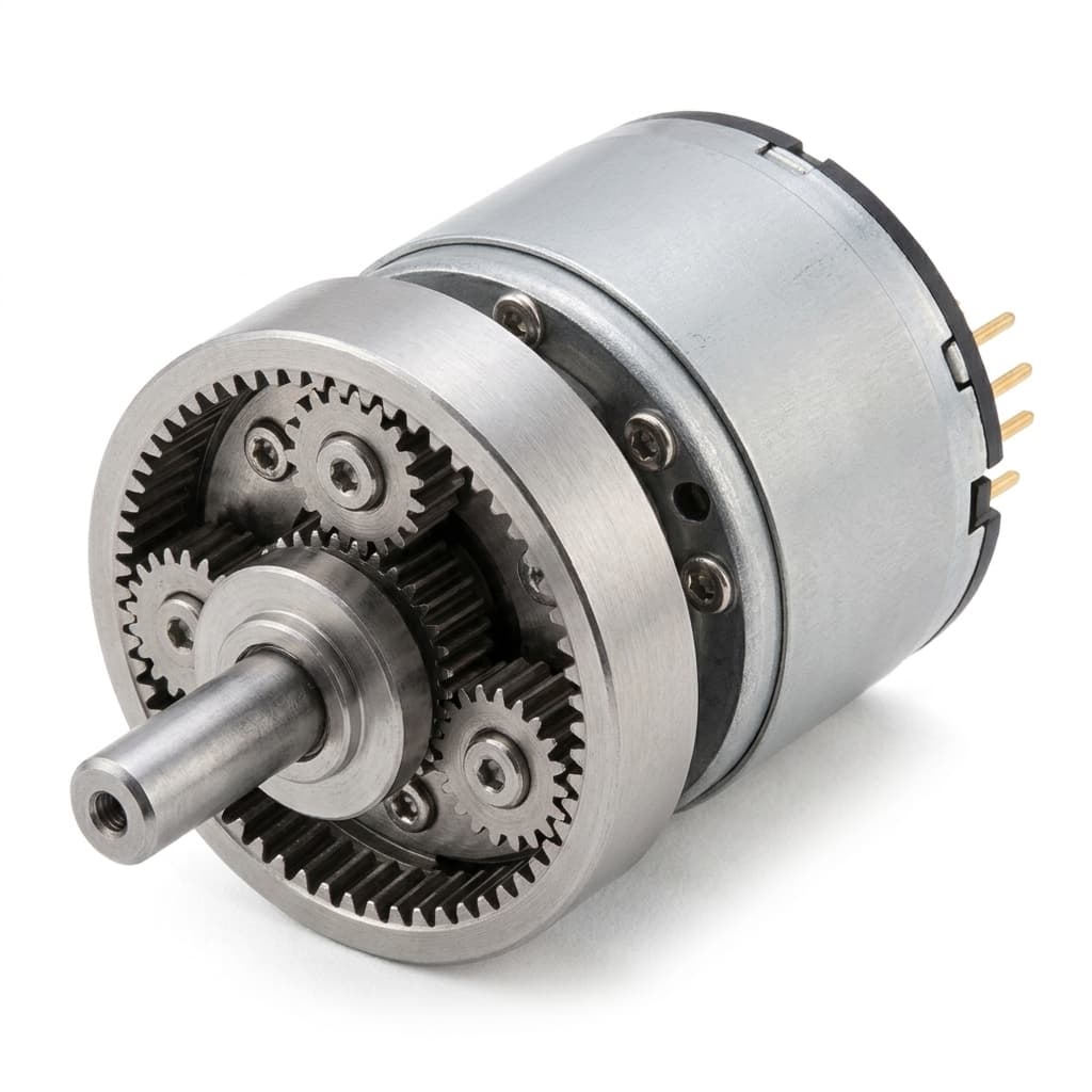
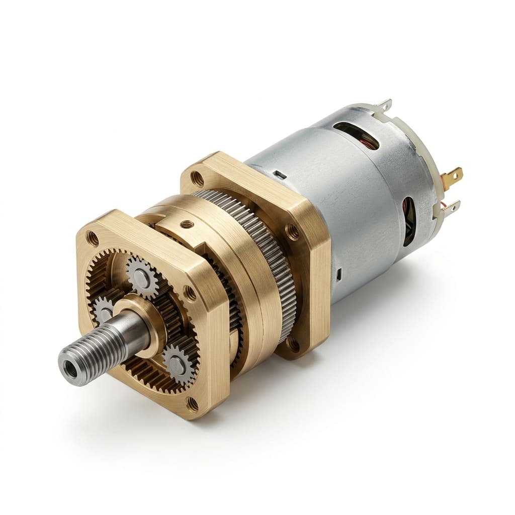
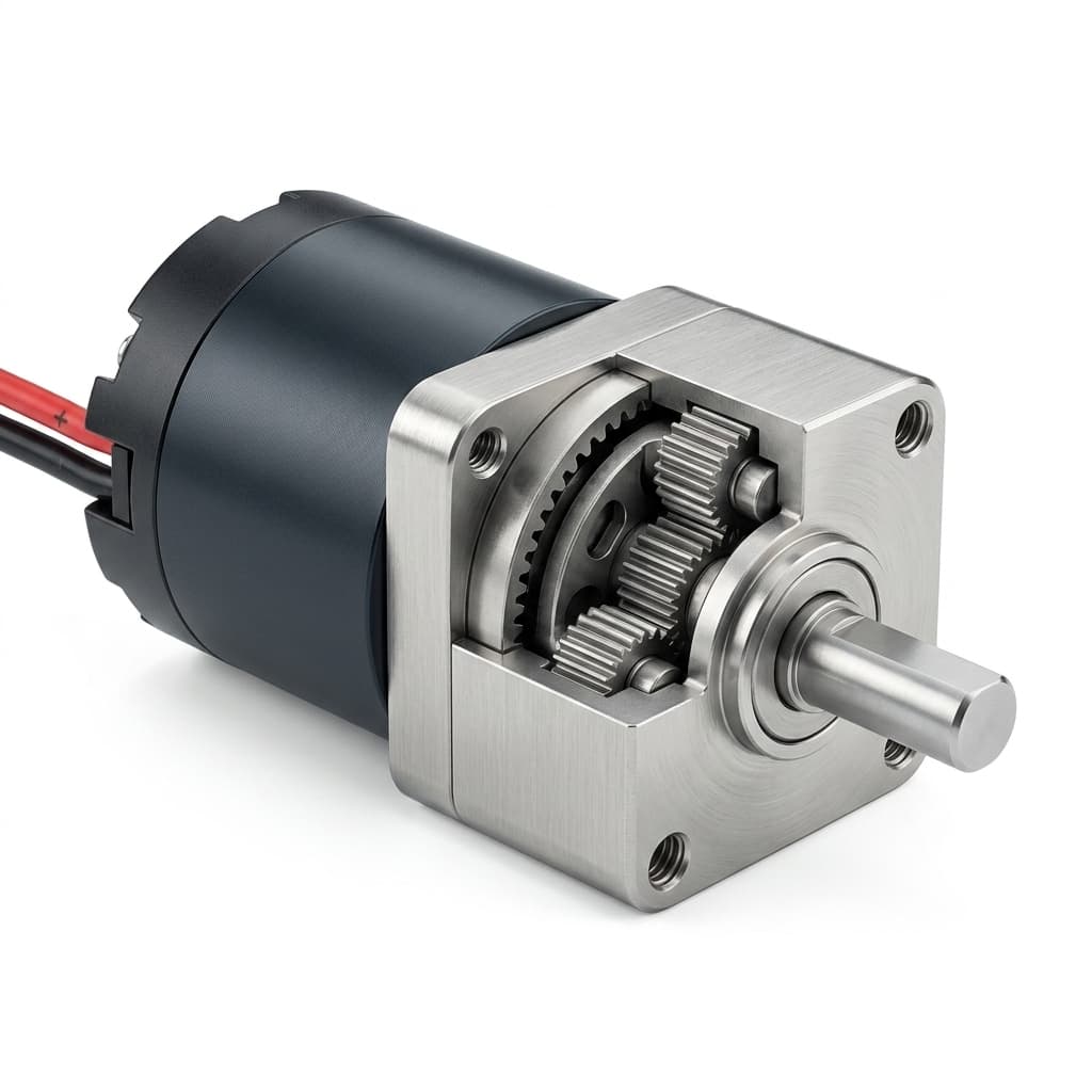
Right angle planetary gear motor for robot joint and AGV module development

Solution Highlights

  • High-torque 16mm, 22mm, 36mm, and 42mm metal gear options
  • Low-backlash review for reversing motion and compact robot joints
  • Encoder, Hall, shaft, and flange customization for OEM modules

Common Use Cases

  • AGV/AMR Drive Wheels
  • Service Robot Joints
  • Robot Vacuum Chassis Lift
  • Inspection Crawlers
  • Micro UAV Mechanisms
  • Humanoid Hand and Gripper Actuators

Implementation Focus

  • Compact-space power density in constrained 16mm, 22mm, 36mm, and 42mm envelopes
  • Low backlash and reversing accuracy for joints, lifts, steering, and navigation axes
  • Metal gear material, carrier plate, shaft hardness, and grease selection for shock or stall events
  • Drive-wheel radial load, axial load, bearing stack, and output flange support
  • Encoder, Hall, or controller feedback integration with cable strain relief
  • Battery runtime, thermal rise, braking behavior, and back-drive risk on ramps

Application Buyer Review Path

Align Fit, Control, Supply, and Quality Before Sampling

Application buyers usually need more than a product suggestion. Use this review path to connect mechanical fit, controls, quote scope, and validation evidence before a sample is approved.

Buyer RoleDecision CheckPage EvidenceNext Step
Mechanical / System EngineeringLoad path, available OD and length, shaft datum, flange geometry, cable exit, radial load, and mating CAD revision.Application intake, implementation focus, selection logic, CAD/STEP panel, and related product routes.Request CAD / STEP
Electrical / ControlsVoltage window, current limit, driver type, feedback signal, EMI concern, braking behavior, and duty cycle.Evaluation matrix, feedback route, validation package, and sample test evidence request.Review encoder options
Procurement / ProgramPrototype quantity, annual volume, sample timing, quote scope, destination, and approved supplier workflow.RFQ checklist, WhatsApp handoff, email template, export file scope, and related OEM support links.Send RFQ
Quality / NPIDrawing revision, CTQ dimensions, torque-speed test condition, noise/backlash method, EOL limits, and lot traceability.Production and QC flow, risk controls, validation package, and buyer-defined evidence scope.Quality evidence

Mechanical / System Engineering

Decision Check
Load path, available OD and length, shaft datum, flange geometry, cable exit, radial load, and mating CAD revision.
Page Evidence
Application intake, implementation focus, selection logic, CAD/STEP panel, and related product routes.
Next Step
Request CAD / STEP

Electrical / Controls

Decision Check
Voltage window, current limit, driver type, feedback signal, EMI concern, braking behavior, and duty cycle.
Page Evidence
Evaluation matrix, feedback route, validation package, and sample test evidence request.
Next Step
Review encoder options

Procurement / Program

Decision Check
Prototype quantity, annual volume, sample timing, quote scope, destination, and approved supplier workflow.
Page Evidence
RFQ checklist, WhatsApp handoff, email template, export file scope, and related OEM support links.
Next Step
Send RFQ

Quality / NPI

Decision Check
Drawing revision, CTQ dimensions, torque-speed test condition, noise/backlash method, EOL limits, and lot traceability.
Page Evidence
Production and QC flow, risk controls, validation package, and buyer-defined evidence scope.
Next Step
Quality evidence

Application RFQ Intake

Translate the Application Into Motor Selection Inputs

The first review should capture load, speed, space, validation, and compliance constraints, not just a motor part number. This keeps the recommended gear ratio, shaft, feedback, and test plan tied to the real machine.

RFQ InputExamples to ProvideEngineering Output
Load and motion profileContinuous torque, peak torque, stall/jam event, stroke, angle, wheel load, or pump cycle.Frames the motor diameter, winding, ratio, gear material, and torque reserve before sample selection.
Speed, timing, and ratio boundaryNo-load RPM, loaded output RPM, actuation time, known ratio, or acceptable speed tolerance.Creates the candidate ratio table with rated-load speed, current, efficiency, and thermal expectation.
Noise, backlash, and repeatabilitydB limit, measurement distance, arcmin or degree backlash target, reversing frequency, positioning need.Separates POM, hybrid, metal, low-backlash, encoder, and Hall-feedback paths early.
Envelope and interface controlTarget OD, max length, shaft drawing, flange datum, cable exit, connector, mating CAD revision.Prevents CAD/STEP mismatch and keeps shaft, mounting, harness, and packaging changes visible.
Validation and production scopePrototype quantity, annual volume, life target, destination, RoHS/REACH, ISO file, packing rules.Defines sample evidence, EOL test limits, compliance files, lead time, and production quote assumptions.

Load and motion profile

Examples to Provide
Continuous torque, peak torque, stall/jam event, stroke, angle, wheel load, or pump cycle.
Engineering Output
Frames the motor diameter, winding, ratio, gear material, and torque reserve before sample selection.

Speed, timing, and ratio boundary

Examples to Provide
No-load RPM, loaded output RPM, actuation time, known ratio, or acceptable speed tolerance.
Engineering Output
Creates the candidate ratio table with rated-load speed, current, efficiency, and thermal expectation.

Noise, backlash, and repeatability

Examples to Provide
dB limit, measurement distance, arcmin or degree backlash target, reversing frequency, positioning need.
Engineering Output
Separates POM, hybrid, metal, low-backlash, encoder, and Hall-feedback paths early.

Envelope and interface control

Examples to Provide
Target OD, max length, shaft drawing, flange datum, cable exit, connector, mating CAD revision.
Engineering Output
Prevents CAD/STEP mismatch and keeps shaft, mounting, harness, and packaging changes visible.

Validation and production scope

Examples to Provide
Prototype quantity, annual volume, life target, destination, RoHS/REACH, ISO file, packing rules.
Engineering Output
Defines sample evidence, EOL test limits, compliance files, lead time, and production quote assumptions.

Application Evaluation Matrix

Evaluation MetricTypical RangeBuyer Relevance
Torque Density16/22mm for mid-load modules; 36/42mm BLDC candidates for heavy drive axesHelps select a motor frame that fits compact robot spaces without losing start torque or continuous torque margin.
Backlash Target<8-12 arcmin economy, <3-7 arcmin high precision, <1-2 arcmin ultra-precision request reviewLow-backlash targets reduce positioning drift in robot joints, lift modules, steering, and reversing drive cycles.
Radial and Axial Load RatingBy frame size, shaft geometry, bearing stack, and flange supportDefines whether drive wheel loads need reinforced output support.
Feedback ResolutionEncoder CPR, Hall signal, or controller-defined feedbackSupports odometry, speed matching, joint repeatability, stall detection, and production EOL signal checks.
Thermal Rise and EfficiencyVoltage, load, duty cycle, and chassis heat-path dependentBattery-powered robots need enough torque reserve without overheating enclosed motor cavities.
Back-drive and Braking BehaviorRatio, motor type, load, and brake strategy dependentDetermines if the AGV will roll down a ramp when power is cut.

Torque Density

Typical Range
16/22mm for mid-load modules; 36/42mm BLDC candidates for heavy drive axes
Buyer Relevance
Helps select a motor frame that fits compact robot spaces without losing start torque or continuous torque margin.

Backlash Target

Typical Range
<8-12 arcmin economy, <3-7 arcmin high precision, <1-2 arcmin ultra-precision request review
Buyer Relevance
Low-backlash targets reduce positioning drift in robot joints, lift modules, steering, and reversing drive cycles.

Radial and Axial Load Rating

Typical Range
By frame size, shaft geometry, bearing stack, and flange support
Buyer Relevance
Defines whether drive wheel loads need reinforced output support.

Feedback Resolution

Typical Range
Encoder CPR, Hall signal, or controller-defined feedback
Buyer Relevance
Supports odometry, speed matching, joint repeatability, stall detection, and production EOL signal checks.

Thermal Rise and Efficiency

Typical Range
Voltage, load, duty cycle, and chassis heat-path dependent
Buyer Relevance
Battery-powered robots need enough torque reserve without overheating enclosed motor cavities.

Back-drive and Braking Behavior

Typical Range
Ratio, motor type, load, and brake strategy dependent
Buyer Relevance
Determines if the AGV will roll down a ramp when power is cut.

Sample Qualification Plan

Convert This Use Case Into Pass/Fail Evidence

These checks help engineering, procurement, and quality teams turn the application discussion into sample acceptance criteria before CAD freeze or pilot procurement.

WorkstreamBuyer QuestionEvidence to PreparePass Signal
Drive load and tractionWill the motor keep start torque and speed margin with the real payload, wheel, ramp, and voltage sag?Payload, wheel diameter, ramp angle, ground speed, voltage window, current limit, and loaded current trace.Starts cleanly at minimum voltage, meets loaded speed, and stays below agreed current and temperature limits.
Shock and gearbox survivalCan the gear stack survive wall contact, wheel impact, stall, or service-robot collision events?Impact assumption, stall duration, controller current limit, shaft load direction, and post-test backlash check.No tooth damage, no abnormal noise rise, and backlash or output play remains inside the agreed limit.
Feedback and navigation signalCan the controller read stable Hall or encoder signals for odometry, speed match, or joint repeatability?Encoder CPR, signal voltage, pinout, cable length, shielding route, driver input, and EOL signal criteria.Signal edges remain stable under loaded motion, cable movement, and current spikes on the target controller.
Battery and thermal dutyDoes the selected motor protect runtime and thermal margin during repeated start-stop missions?Mission duty sequence, ambient temperature, enclosure heat path, current limit, and continuous/peak torque split.Thermal rise stabilizes inside the buyer limit while duty-cycle current stays within the battery budget.

Drive load and traction

Buyer Question
Will the motor keep start torque and speed margin with the real payload, wheel, ramp, and voltage sag?
Evidence to Prepare
Payload, wheel diameter, ramp angle, ground speed, voltage window, current limit, and loaded current trace.
Pass Signal
Starts cleanly at minimum voltage, meets loaded speed, and stays below agreed current and temperature limits.

Shock and gearbox survival

Buyer Question
Can the gear stack survive wall contact, wheel impact, stall, or service-robot collision events?
Evidence to Prepare
Impact assumption, stall duration, controller current limit, shaft load direction, and post-test backlash check.
Pass Signal
No tooth damage, no abnormal noise rise, and backlash or output play remains inside the agreed limit.

Feedback and navigation signal

Buyer Question
Can the controller read stable Hall or encoder signals for odometry, speed match, or joint repeatability?
Evidence to Prepare
Encoder CPR, signal voltage, pinout, cable length, shielding route, driver input, and EOL signal criteria.
Pass Signal
Signal edges remain stable under loaded motion, cable movement, and current spikes on the target controller.

Battery and thermal duty

Buyer Question
Does the selected motor protect runtime and thermal margin during repeated start-stop missions?
Evidence to Prepare
Mission duty sequence, ambient temperature, enclosure heat path, current limit, and continuous/peak torque split.
Pass Signal
Thermal rise stabilizes inside the buyer limit while duty-cycle current stays within the battery budget.

Product Family Routing

Route This Application to the Right Motor Family

A solution page should make the next product review obvious. Match the dominant application signal to a product family, then send the listed inputs so engineering can confirm the route.

Application SignalRecommended Product RouteInputs to ConfirmReview
High torque, shock load, wheel load, breakaway torque, or jam conditionHigh-torque miniature gear motors or metal gear micro planetary drives with reinforced gear stack review.Share continuous torque, peak torque, stall time, shaft load, duty cycle, and current limit.High torque motors
Quiet patient-adjacent, indoor, optical, or residential motion targetLow-noise, coreless, POM, or hybrid gear stage route before moving to metal gears.Share dB limit, measurement distance, enclosure condition, load, temperature, and life target.Low noise motors
Positioning, odometry, repeatability, stall detection, or closed-loop controlEncoder or Hall-feedback planetary gear motor with defined signal and EOL checks.Share CPR, signal voltage, controller input, cable route, pinout, and target resolution.Encoder motors
Custom shaft, flange, connector, harness, bracket, or module packagingCustom OEM micro drive assembly with drawing revision, tooling boundary, and production handoff.Attach mating drawing, shaft profile, flange datum, connector model, packing rule, and annual volume.OEM assemblies
Material, backlash, noise, and durability tradeoff is not frozenPOM, hybrid, MIM metal, or low-backlash route reviewed against the real application load.Share noise target, reversing frequency, backlash limit, shock condition, grease concern, and cost band.Material guide

High torque, shock load, wheel load, breakaway torque, or jam condition

Recommended Product Route
High-torque miniature gear motors or metal gear micro planetary drives with reinforced gear stack review.
Inputs to Confirm
Share continuous torque, peak torque, stall time, shaft load, duty cycle, and current limit.
Review
High torque motors

Quiet patient-adjacent, indoor, optical, or residential motion target

Recommended Product Route
Low-noise, coreless, POM, or hybrid gear stage route before moving to metal gears.
Inputs to Confirm
Share dB limit, measurement distance, enclosure condition, load, temperature, and life target.
Review
Low noise motors

Positioning, odometry, repeatability, stall detection, or closed-loop control

Recommended Product Route
Encoder or Hall-feedback planetary gear motor with defined signal and EOL checks.
Inputs to Confirm
Share CPR, signal voltage, controller input, cable route, pinout, and target resolution.
Review
Encoder motors

Custom shaft, flange, connector, harness, bracket, or module packaging

Recommended Product Route
Custom OEM micro drive assembly with drawing revision, tooling boundary, and production handoff.
Inputs to Confirm
Attach mating drawing, shaft profile, flange datum, connector model, packing rule, and annual volume.
Review
OEM assemblies

Material, backlash, noise, and durability tradeoff is not frozen

Recommended Product Route
POM, hybrid, MIM metal, or low-backlash route reviewed against the real application load.
Inputs to Confirm
Share noise target, reversing frequency, backlash limit, shock condition, grease concern, and cost band.
Review
Material guide

Selection Logic

Decision PointRecommended PathValidation Input
AGV/AMR wheel versus robot joint or lift axisUse reinforced output bearings, metal gear stages, and BLDC or encoder feedback for wheel loads; use compact low-backlash DC or coreless builds for lighter joints, grippers, and lift modules.Wheel load, radial force direction, shaft coupling, joint repeatability, lift load, and expected impact events.
Frame size and torque classReview 16mm and 22mm gear motors for compact mid-load modules, then move to 36mm or 42mm BLDC planetary motors when continuous torque, payload, or wheel load rises.Available diameter and length, output torque, speed target, ratio, thermal path, and life target.
Low backlash versus shock robustness and costChoose the lowest backlash class only where repeatability matters; high shock wheel modules may need a stronger metal gear stack and current limiting more than ultra-low backlash.Backlash target in arcmin, reversing frequency, impact profile, acceptable cost band, and measurement method.
Closed-loop navigation requirementChoose encoder or Hall feedback when odometry, speed matching, or stall detection must be confirmed by the controller.Pulse count, voltage, controller input type, cable length, and target positioning resolution.
Battery runtime versus torque reserveCompare BLDC and brushed planetary options against continuous torque, peak current, duty cycle, and thermal path.Battery voltage window, current limit, duty sequence, ambient temperature, and chassis heat path.
Hold, brake, or freewheel behaviorDefine whether the axis must hold position, resist back-drive, or coast freely before choosing ratio, motor type, brake strategy, or mechanical compliance.Ramp angle, payload, power-cut state, emergency stop behavior, and acceptable rollback distance.

AGV/AMR wheel versus robot joint or lift axis

Recommended Path
Use reinforced output bearings, metal gear stages, and BLDC or encoder feedback for wheel loads; use compact low-backlash DC or coreless builds for lighter joints, grippers, and lift modules.
Validation Input
Wheel load, radial force direction, shaft coupling, joint repeatability, lift load, and expected impact events.

Frame size and torque class

Recommended Path
Review 16mm and 22mm gear motors for compact mid-load modules, then move to 36mm or 42mm BLDC planetary motors when continuous torque, payload, or wheel load rises.
Validation Input
Available diameter and length, output torque, speed target, ratio, thermal path, and life target.

Low backlash versus shock robustness and cost

Recommended Path
Choose the lowest backlash class only where repeatability matters; high shock wheel modules may need a stronger metal gear stack and current limiting more than ultra-low backlash.
Validation Input
Backlash target in arcmin, reversing frequency, impact profile, acceptable cost band, and measurement method.

Closed-loop navigation requirement

Recommended Path
Choose encoder or Hall feedback when odometry, speed matching, or stall detection must be confirmed by the controller.
Validation Input
Pulse count, voltage, controller input type, cable length, and target positioning resolution.

Battery runtime versus torque reserve

Recommended Path
Compare BLDC and brushed planetary options against continuous torque, peak current, duty cycle, and thermal path.
Validation Input
Battery voltage window, current limit, duty sequence, ambient temperature, and chassis heat path.

Hold, brake, or freewheel behavior

Recommended Path
Define whether the axis must hold position, resist back-drive, or coast freely before choosing ratio, motor type, brake strategy, or mechanical compliance.
Validation Input
Ramp angle, payload, power-cut state, emergency stop behavior, and acceptable rollback distance.

Production and QC Flow

StageControl PointBuyer Evidence
Motion axis requirement reviewClassify the module as drive wheel, joint, lift, gripper, crawler, or UAV mechanism, then freeze torque, speed, backlash, feedback, and envelope targets.Module drawing, torque-speed target, backlash target, feedback requirement, and operating sequence.
Backlash, torque, and impact validationMeasure output speed, current draw, backlash, thermal rise, noise, encoder signal stability, and shock response under representative load.Sample test report with voltage, load, temperature, backlash method, impact notes, and feedback checks.
Cable, feedback, and thermal reviewValidate connector pinout, cable strain relief, Hall or encoder signal quality, thermal path, and controller current limit before pilot tooling.Pinout drawing, cable route, EOL signal criteria, current limit, and thermal run record.
Pilot and production releaseFreeze shaft drawing, flange geometry, connector pinout, EOL speed/current/noise/backlash limits, packaging protection, and lot traceability.Approved drawing revision, EOL criteria, lot label plan, and outgoing inspection record.

Motion axis requirement review

Control Point
Classify the module as drive wheel, joint, lift, gripper, crawler, or UAV mechanism, then freeze torque, speed, backlash, feedback, and envelope targets.
Buyer Evidence
Module drawing, torque-speed target, backlash target, feedback requirement, and operating sequence.

Backlash, torque, and impact validation

Control Point
Measure output speed, current draw, backlash, thermal rise, noise, encoder signal stability, and shock response under representative load.
Buyer Evidence
Sample test report with voltage, load, temperature, backlash method, impact notes, and feedback checks.

Cable, feedback, and thermal review

Control Point
Validate connector pinout, cable strain relief, Hall or encoder signal quality, thermal path, and controller current limit before pilot tooling.
Buyer Evidence
Pinout drawing, cable route, EOL signal criteria, current limit, and thermal run record.

Pilot and production release

Control Point
Freeze shaft drawing, flange geometry, connector pinout, EOL speed/current/noise/backlash limits, packaging protection, and lot traceability.
Buyer Evidence
Approved drawing revision, EOL criteria, lot label plan, and outgoing inspection record.

Design Freeze Risk Check

Failure Modes to Close Before Pilot Release

Most application failures are not caused by the gear ratio alone. Close these checks before the motor family, drawing revision, and validation method are locked.

Failure ModeEarly SignalPrevention
Torque reserve disappears after the real fixture is installedNo-load speed looks acceptable, but current rises or motion stalls under seal friction, wheel load, spring force, or end-stop impact.Quote against continuous, peak, and stall conditions with voltage sag, current limit, duty cycle, and thermal path included.
CAD fit passes once, then fails after shaft or connector revisionThe gearbox OD fits the enclosure, but the shaft flat, flange datum, cable exit, connector, or bend radius changes late.Freeze drawing revision, mating CAD, cable route, shaft datum, and connector clearance before pilot release.
Noise or backlash is rejected because the method was unclearBuyer and supplier use different load, distance, preload, fixture, background noise, or backlash measurement conditions.Define dB distance, load fixture, backlash preload, direction changes, and pass/fail limit before sample testing.
Thermal, EMI, or feedback issues appear only in pilot buildBench samples pass, but enclosure heat path, controller current limit, cable routing, or encoder signal quality changes in the real device.Validate the motor with buyer-like enclosure, driver, cable route, duty profile, and EOL signal checks.
Approved samples drift when the program moves to productionPrototype BOM, gear material, grease, label, packing, or EOL limit is not tied to an approved revision.Keep approved sample record, BOM option, drawing revision, EOL criteria, lot labels, and outgoing inspection plan together.

Torque reserve disappears after the real fixture is installed

Early Signal
No-load speed looks acceptable, but current rises or motion stalls under seal friction, wheel load, spring force, or end-stop impact.
Prevention
Quote against continuous, peak, and stall conditions with voltage sag, current limit, duty cycle, and thermal path included.

CAD fit passes once, then fails after shaft or connector revision

Early Signal
The gearbox OD fits the enclosure, but the shaft flat, flange datum, cable exit, connector, or bend radius changes late.
Prevention
Freeze drawing revision, mating CAD, cable route, shaft datum, and connector clearance before pilot release.

Noise or backlash is rejected because the method was unclear

Early Signal
Buyer and supplier use different load, distance, preload, fixture, background noise, or backlash measurement conditions.
Prevention
Define dB distance, load fixture, backlash preload, direction changes, and pass/fail limit before sample testing.

Thermal, EMI, or feedback issues appear only in pilot build

Early Signal
Bench samples pass, but enclosure heat path, controller current limit, cable routing, or encoder signal quality changes in the real device.
Prevention
Validate the motor with buyer-like enclosure, driver, cable route, duty profile, and EOL signal checks.

Approved samples drift when the program moves to production

Early Signal
Prototype BOM, gear material, grease, label, packing, or EOL limit is not tied to an approved revision.
Prevention
Keep approved sample record, BOM option, drawing revision, EOL criteria, lot labels, and outgoing inspection plan together.

Validation Package

Evidence Buyers Can Request Before Pilot Release

Application pages should lead toward drawings, sample evidence, and production assumptions. These files are scoped during RFQ so buyers know what can be verified before design freeze.

EvidenceWhat It IncludesBuyer Use
Performance checkVoltage, no-load speed, rated-load speed, current, torque point, ratio, and temperature note.Confirms the selected motor matches the required operating point before pilot procurement.
Mechanical file setOutline drawing, shaft/flange revision, STEP/IGES availability, cable exit, connector, and label notes.Lets mechanical teams freeze enclosure, mating part, harness route, and incoming inspection dimensions.
Application-specific test noteNoise, backlash, cycle life, thermal rise, radial load, EMI, or holding-force check as required.Turns the market- or device-specific concern into a measurable sample approval criterion.
Production and export fileBOM option, EOL speed/current limits, RoHS/REACH or buyer file scope, packing, shipment destination.Keeps repeat orders aligned after prototype approval and reduces qualification drift.

Performance check

What It Includes
Voltage, no-load speed, rated-load speed, current, torque point, ratio, and temperature note.
Buyer Use
Confirms the selected motor matches the required operating point before pilot procurement.

Mechanical file set

What It Includes
Outline drawing, shaft/flange revision, STEP/IGES availability, cable exit, connector, and label notes.
Buyer Use
Lets mechanical teams freeze enclosure, mating part, harness route, and incoming inspection dimensions.

Application-specific test note

What It Includes
Noise, backlash, cycle life, thermal rise, radial load, EMI, or holding-force check as required.
Buyer Use
Turns the market- or device-specific concern into a measurable sample approval criterion.

Production and export file

What It Includes
BOM option, EOL speed/current limits, RoHS/REACH or buyer file scope, packing, shipment destination.
Buyer Use
Keeps repeat orders aligned after prototype approval and reduces qualification drift.

CAD / STEP Request

Request Outline Drawings Before You Freeze the Mechanical Design

Share the mating envelope and target duty data so sales engineering can confirm whether an existing outline drawing, STEP/IGES file, or custom shaft and flange proposal is suitable for your project.

1

Installation envelope, mounting pattern, shaft interface, and cable exit.

2

Voltage, loaded speed, torque, gear ratio, duty cycle, noise, and backlash limits.

3

Preferred CAD format, drawing revision, prototype quantity, destination, and compliance notes.

Fields engineering checks before sharing a model

Product fit
Diameter, gearbox length, motor family, shaft style, flange pattern, and cable or connector exit.
Performance target
Voltage, loaded speed, continuous torque, peak or stall torque, ratio, duty cycle, life, noise, and backlash.
Mechanical interface
Mating drawing revision, installation clearance, radial or axial load, tolerance priority, and assembly sequence.
Release package
2D outline, STEP/IGES envelope, custom shaft/flange review, datasheet values, and quality evidence scope.

Useful before CAD freeze

Estimate ratio and torque firstCompare POM, hybrid, and metal gearsAlign quality evidence scope
Email CAD requestWhatsApp engineeringOpen CAD request form

CAD files are shared by project fit and revision status. For custom shafts, flanges, cable routing, or gearbox interfaces, attach the mating drawing so the first CAD exchange uses the correct mechanical boundary.

RFQ Preparation Checklist

  1. Robot module type: AGV/AMR wheel, service robot joint, gripper, vacuum lift, UAV mechanism, or inspection crawler
  2. Output torque: continuous, peak, stall limit, speed target, and ratio target
  3. Backlash limit in arcmin or degrees, plus the intended measurement method
  4. Wheel diameter, payload, ramp angle, ground speed, radial load, and expected impact events
  5. Joint angle, lift stroke, reversing frequency, and positioning repeatability
  6. Voltage, current limit, driver type, encoder or Hall feedback, pinout, and cable route
  7. Custom shaft, flange, mounting drawing, and axial or radial load direction
  8. Duty cycle, life target, temperature range, noise target, and IP or sealing requirement

Risk and Mitigation

  • Positioning drift from backlash or stack-up: Set a measurable backlash target, confirm the test method, and match the gear class to the robot axis tolerance instead of buying by ratio alone.
  • Gear tooth or carrier failure under impact: Review metal gear material, carrier plate strength, current limit, stall time, and shock events before sample release.
  • Output shaft or bearing overload: Shaft geometry, material, hardness, and bearing support are reviewed against wheel load and coupling.
  • Encoder noise or cable damage: Define connector pinout, cable route, shielding, strain relief, and EOL signal checks early in the prototype stage.
  • Thermal derating in enclosed chassis: Thermal potting, winding selection, or chassis heat-path design can be reviewed for enclosed BLDC drive packages.
  • Braking or back-drive mismatch on ramps: Confirm whether the axis should hold, coast, or be actively braked, then validate with ramp angle, payload, and power-cut tests.

Recommended Products

Right angle planetary gear motor for compact service robot and AGV layouts
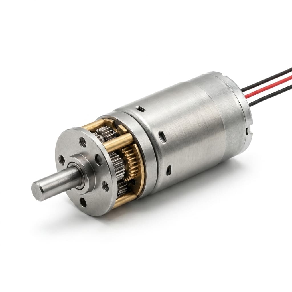
Low-profile right angle planetary gearbox for robot chassis and crawler actuators
Metal gear right angle motor option for high-torque robotic mechanisms
OEM right angle planetary drive for constrained robot mounting geometry
Compact planetary gear motor assembly for AGV auxiliary actuator design

Buyer FAQ

Can you supply low-backlash gearboxes for robot joints?

Yes. Backlash must be treated as an application target, so the RFQ should include the arcmin or degree limit, torque load, direction changes, and measurement method.

How should backlash be specified for robotics projects?

State the allowed output free play under a known preload or torque condition. Economy, high-precision, and ultra-precision targets can be reviewed, but final values depend on frame size, ratio, gear material, and production tolerance.

Should an AGV drive wheel use brushed DC or BLDC?

BLDC is usually preferred when runtime, thermal margin, and closed-loop control matter. Brushed DC can still fit cost-sensitive or lighter duty modules when the duty cycle and life target are realistic.

Can you customize the shaft, flange, encoder, and connector?

Yes. Custom output shafts, flats, D-cuts, flanges, brackets, encoder options, Hall feedback, cable length, and connector pinouts can be reviewed from the module drawing.

Can you withstand continuous start-stop cycles?

Start-stop durability depends on load, shock, current limit, and thermal path; sample tests should reproduce the duty profile before release.

Do you supply the wheel as well?

Yes, we offer integrated polyurethane (PU) wheels mounted directly to the planetary gearbox flange.

What happens if the robot hits a wall?

For high-risk environments, inline slip clutches, current limits, or mechanical compliance can be reviewed to reduce shock transfer into the gear teeth.

Related Resources

  • High Torque Miniature Motors
  • Low Backlash Micro Planetary Gear Motors
  • Metal Gear Micro Planetary Drives
  • Micro BLDC Planetary Gear Motor
  • Encoder Micro Planetary Gear Motor
  • Custom Shaft & Flange Design
  • Backlash Measurement Guide
  • Gearbox Failure Analysis Guide
  • Testing & Validation Support
  • Contact Sales Engineering

Application Qualification Review

Ready to Qualify This Application?

Send the application module, target load, speed, torque, envelope, voltage, quantity, drawing status, and validation concerns. Sales engineering can then confirm whether this solution route, another product family, or an OEM assembly path is safer.

WhatsApp: +86 18857971991. Email: [email protected].

WhatsApp ReviewSend RFQRequest CAD / STEP

Inquiry Email

[email protected]

Email app

Include OD/length, voltage, torque, loaded speed, ratio, drawings, quantity, and destination.

Instant Chat

+86 18857971991

Chat on WhatsApp

Fast channel for clarifying specs, drawings, and sample timing.