
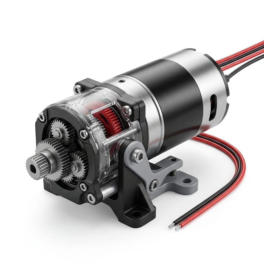
How to Choose the Right Micro Planetary Gear Motor for Your Application
A comprehensive buyer-side engineering guide on sizing, torque requirements, gear materials, and selecting the optimal micro planetary gear motor architecture.
When specifying a micro planetary gearbox under 32mm, relying only on theoretical holding torque or input voltage can create pilot-build failures.
Use the operating logic below to size the gearbox, balance BOM cost, and reduce the risk of mechanical lockup in the field.
1. Define the True Operating Torque
Often, engineers calculate the theoretical load and select a motor based on its peak torque. However, planetary gearboxes have very strict continuous torque ratings based on their planetary carrier material and gear module (tooth size).
- Continuous Torque (Rated Torque): The load the motor can handle 24/7 without thermal or mechanical degradation.
- Peak Torque (Stall Torque): The maximum load permissible for very short durations (e.g., overcoming initial friction or a momentary stall).
Actionable Tip: Always select a motor where your continuous operating load falls within 50% to 70% of the motor's rated continuous torque. If your application calculates a continuous load of 1.0 Nm, specify a gearbox rated for at least 1.5 Nm continuous.
2. Speed, Reduction Ratio, and Efficiency
Planetary gearboxes achieve high torque in a compact form factor by distributing the load across multiple planetary gears. Higher reduction ratios require more gear stages (e.g., stacking 3 or 4 stages end-to-end).
However, each additional stage introduces two critical penalties:
- Efficiency Drop: Each planetary stage typically reduces mechanical efficiency by about 10–15%.
- A 1-stage gearbox (e.g., 4:1 ratio) may have an efficiency of ~90%.
- A 4-stage gearbox (e.g., 256:1 ratio) might drop to ~60% efficiency.
- Result: The system draws more current and generates more heat to move the same load.
For the complete formula path, use the planetary gear ratio and output torque calculation guide before opening the calculator.
- Backlash Accumulation: More stages mean more accumulated mechanical play (backlash). If your application requires high precision (e.g., robotic joints or optical lens focusing), you may need to specify a low-backlash design (≤ 1.5 degrees) or limit the gearbox to 2 stages.
3. Selecting the Right Gear Material
Not all planetary gears behave the same way. The material of the sun and planetary gears affects noise level, torque capacity, wear behavior, and unit cost.
| Gear Material | Torque Capacity | Acoustic Noise | Best Use Case | Cost Level |
|---|---|---|---|---|
| POM / Plastic | Low (≤ 0.5 Nm) | Very Low (Quiet) | Medical devices, smart home automation. | $ |
| Powder Metallurgy (PM) | Medium (1.0 - 5.0 Nm) | Moderate | Valve actuators, smart locks, power tools. | $$ |
| Machined Steel (Hobbing) | High (≥ 5.0 Nm) | Higher | Heavy-duty robotics, industrial valves. | $$$ |
[!NOTE] Engineering Review: Pump Duty Cycle A pump program that is sized only from peak torque can overload plastic stages during long duty cycles. Reviewing thermal rise, stage count, and gear material early helps decide whether a hybrid PM/steel gear train is justified before pilot builds.
Note: For many noise-sensitive torque profiles, OEMs review a hybrid gearbox: a POM first stage for high-speed noise reduction and PM or steel for later stages where torque is highest.
4. Radial and Axial Shaft Loads
Do not ignore the physical forces acting on the output shaft.
- Radial Load: Pushing sideways against the shaft (e.g., mounting a pulley or belt directly to the motor).
- Axial Load: Pushing directly in or pulling out on the shaft (e.g., a lead screw mechanism).
Standard micro planetary gearboxes use sintered bronze sleeve bearings, which are cost-effective but highly susceptible to wear under radial loads. If your design applies side-loading, you must explicitly specify dual ball bearings on the output shaft during the RFQ. Failure to do so will result in shaft wobble and premature gear failure within 500 hours.
5. Thermal Envelope and Duty Cycle
Micro motors, especially coreless DC motors, can heat up rapidly. Your duty cycle (the ratio of ON time to OFF time) dictates the thermal accumulation. If your application runs continuously, thermal dissipation becomes a primary design constraint. In these scenarios, moving from a 16mm motor to a 22mm motor, or upgrading from a brushed DC motor to a BLDC (Brushless) motor, may be required to keep winding temperature within the approved limit.
The RFQ Data You Actually Need to Send
Do not send only a generic "I need a 12V 100RPM motor" email. For a quotation that can hold up in pilot builds and repeat production, define these parameters:
- Continuous Operating Torque (Nm or kg.cm)
- Maximum Peak/Shock Torque
- Target Output Speed (RPM under load)
- Duty Cycle (e.g., 2 min ON / 5 min OFF)
- Expected Lifespan (Hours)
- Side-load presence (Yes/No)
Give the supplier this data upfront. → Send your parameters to our engineering team here. It reduces back-and-forth and keeps thermal assumptions explicit before samples are built.
More Posts
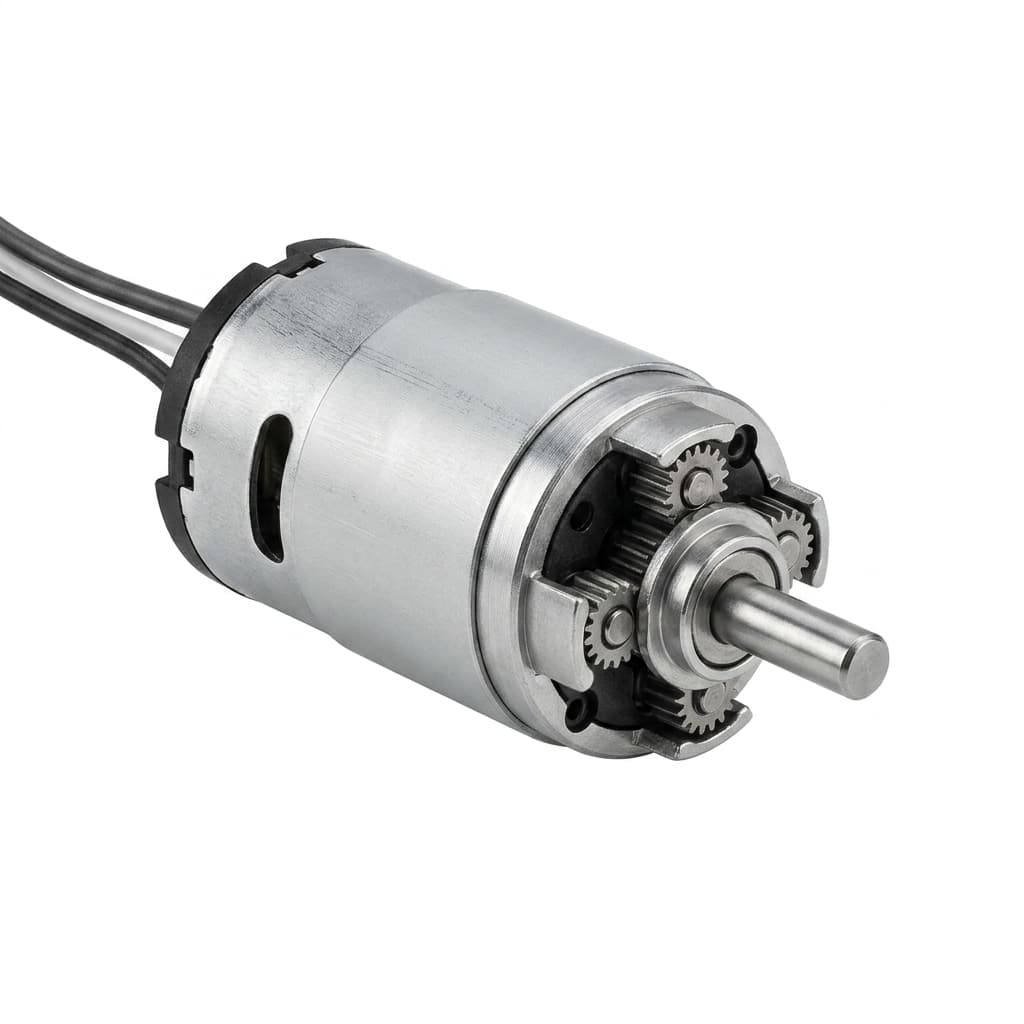
Understanding and Measuring Backlash in Micro Planetary Gearboxes
A practical engineering guide to backlash, arcminutes, static measurement, dynamic reversal behavior, and RFQ data for low-backlash micro planetary gear motor programs.

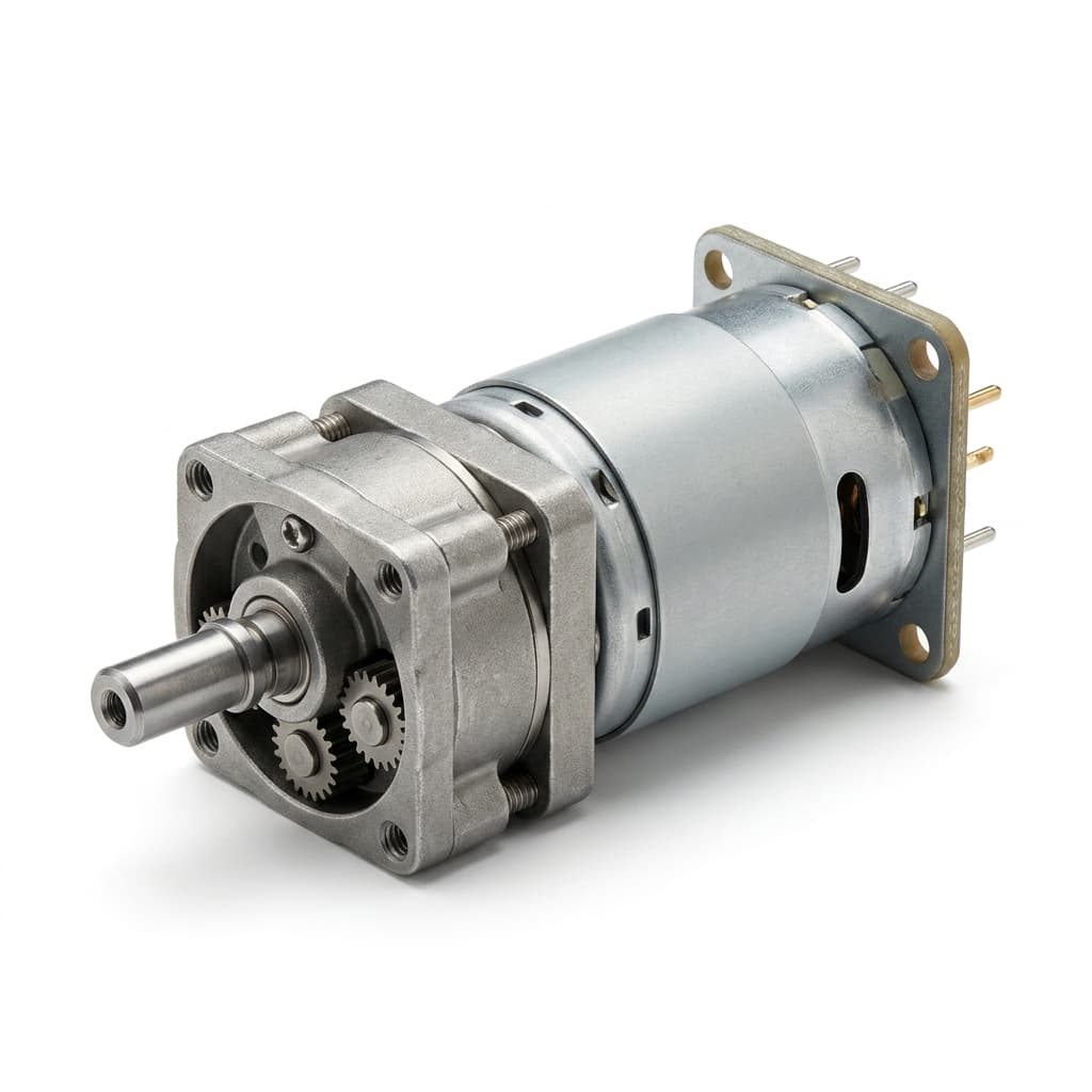
How to Calculate Planetary Gear Ratio and Output Torque
A practical engineering guide to calculating planetary gear reduction ratio, output speed, output torque, efficiency losses, stage count, and RFQ data for micro planetary gear motor projects.
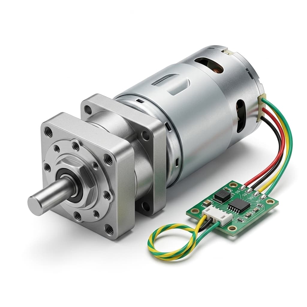
Gear Motor Failure Analysis: Micro-pitting and Tooth Flank Wear in Micro Planetary Gearboxes
Diagnose micro planetary gearbox failures by reading wear patterns, micro-pitting, lubricant breakdown, backlash growth, shaft loads, and validation data before pilot release.