
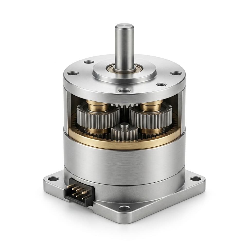
Acoustic Noise Reduction in Micro Planetary Gear Motors: NVH Sizing, Gear Mesh Frequency, and RFQ Acceptance Standards
Reduce micro planetary gear motor noise: calculate mesh frequencies, compare gear materials, and use an RFQ checklist to agree acoustic acceptance tests.
For acoustic noise reduction in micro planetary gear motors, start by measuring the loaded drive at a defined distance and mounting condition. Calculate gear mesh frequencies to locate tonal excitation, then compare gear materials, lubrication, and chassis isolation while checking torque, current, temperature, and life.
Published and technically reviewed: October 27, 2026. Scope: global OEM sourcing of sub-32 mm, fixed-ring planetary gear motors. The calculations below are reproducible design examples, not measured product results. This guide provides no universal dBA, torque, sterilization, or regulatory approval rating; those require the selected assembly's test records.
A motor selected only by catalog torque, nominal voltage, and dimensional fit can become objectionable when installed in a thin-walled chassis. An ambiguous requirement such as “below 40 dBA” leaves distance, background noise, operating point, and structural integration undefined. Use the acceptance template in Section 8, or send your acoustic requirement for engineering review with the mounting drawing and loaded operating point.
1. Physics of Micro Planetary Gear Noise: Airborne vs. Structure-Borne
To eliminate gear noise systematically, engineering teams must separate the acoustic energy into its two transmission pathways: airborne sound radiation and structure-borne vibration transmission.
Primary Noise Mechanisms in Planetary Reducers
- Dynamic Tooth Transmission Error (TTE): As conjugate involute profiles enter and exit mesh, manufacturing imperfections (profile distortion, lead wobble, base pitch error) cause angular velocity fluctuations. The resulting acceleration creates dynamic contact forces between gear teeth.
- Mesh Stiffness Fluctuations (Δk): The number and position of tooth pairs carrying load change during engagement. This periodic stiffness variation can excite the planetary carrier and ring gear housing; its magnitude depends on geometry, load sharing, and tooth modification.
- High Input Pitch-Line Velocity: The first stage is a useful starting point for diagnosis because it runs fastest. Its share of total sound cannot be inferred from speed alone: motor excitation, bearing condition, and housing response also matter.
- Resonant Structural Coupling: Rigid mounting transmits vibration into the device panels. Compare a repeatable component fixture with the actual enclosure at the same loaded speed; the difference is assembly-specific, not a fixed dBA penalty.
2. Diagnosing Gear Mesh Frequency (GMF) and Harmonic Whine
The most irritating acoustic signature produced by micro planetary gear motors is not broadband mechanical friction ("hiss"), but pure tonal whine concentrated in narrow frequency bands.
A-weighted overall level alone does not describe tonal annoyance. Record a narrowband spectrum alongside the overall level, and agree a tonal assessment method rather than predicting perceived quality from dBA alone.
Calculating the Fundamental Gear Mesh Frequency
For an epicyclic planetary train with a stationary ring gear, the fundamental Gear Mesh Frequency (f_GMF) of the first stage is governed by the relative rotational speed between the high-speed sun pinion and the rotating planetary carrier:
f_GMF1 = (n_sun − n_carrier) × z_sun / 60
       = n_motor × (1 − 1/i_1) × z_sun / 60
Where:
n_motor= Input motor speed under load (RPM)z_sun= Tooth count of the primary sun gear, supplied by the gearhead designeri_1= Reduction ratio of the first planetary stage; for this fixed-ring arrangement,i_1 = 1 + z_ring/z_sun
Calculated example, not a motor test
Assume a fixed-ring, sun-input, carrier-output stage with:
- Motor speed under nominal load:
n_motor = 9,600 RPM - First-stage sun gear tooth count:
z_sun = 9 - First-stage reduction ratio:
i_1 = 4.0:1
f_GMF1 = 9,600 × (1 − 1/4) × 9 / 60 = 1,080 HzThe predicted mesh frequency is 1,080 Hz, with harmonics at 2,160 Hz and 3,240 Hz. For a simple unshifted planetary geometry, a 9-tooth sun and 27-tooth ring give a 4:1 ratio and a 9-tooth planet. Such low tooth counts require an undercut/profile-shift review; this arithmetic is not a manufacturable gear drawing. Use the first-stage ratio, not the complete gearbox ratio. For other ring/carrier arrangements, use the absolute relative speed in f_GMF = abs(n_sun − n_carrier) × z_sun / 60.
Figure: calculated frequency markers only. No acoustic measurements or A-weighting response are plotted.
During a controlled speed sweep, mesh-related peaks should move with relative shaft speed. Compare these with motor commutation/PWM components and approximately fixed structural resonances. A peak near the calculated GMF is a diagnostic lead, not proof of a damaged tooth or a predicted sound level.
3. The Stage-by-Stage Pitch Line Velocity Hierarchy
Multi-stage reducers trade speed for torque. A high-speed input stage is a candidate for noise treatment, while downstream stages need increasing torque capacity. Neither noise contribution nor failure location can be assigned solely by stage number.
For a calculated sizing example, assume three fixed-ring stages, each 4:1, each with 90% efficiency, a 9-tooth sun, and a 2.5 mm sun pitch diameter. Input is 9,600 RPM and 0.003 Nm. These are illustrative inputs, not a product rating.
| Stage | Sun input RPM | Carrier output RPM | Calculated GMF | Relative pitch velocity | Input torque (Nm) | Output torque (Nm) |
|---|---|---|---|---|---|---|
| 1 | 9,600 | 2,400 | 1,080 Hz | 0.942 m/s | 0.0030 | 0.0108 |
| 2 | 2,400 | 600 | 270 Hz | 0.236 m/s | 0.0108 | 0.0389 |
| 3 | 600 | 150 | 67.5 Hz | 0.059 m/s | 0.0389 | 0.1400 |
Use v_relative = π × d_sun × abs(n_sun − n_carrier) / 60 with diameter in metres, and T_out = T_in × i × η. Relative pitch velocity is rolling speed in the carrier frame, not local tooth sliding velocity. The total ratio is 64:1 and assumed overall efficiency is 0.9³ = 72.9%.
Before accepting the resulting 0.1400 Nm, check the selected motor's loaded torque-speed curve and thermal limit, and every gear stage's tooth, carrier, bearing, and shaft ratings. The arithmetic does not establish continuous torque capacity or stall survival.
4. Material Selection & Hybrid Architecture: Engineering Trade-Offs
A hybrid architecture combines a polymer input stage with metal downstream stages. It is a candidate when input-stage excitation is important, but material alone cannot establish a dBA limit. Compare candidate samples using identical speed, torque, mounting, run-in, and temperature conditions.
The seven options below are a sourcing decision matrix, not measured rankings or interchangeable product ratings.
| Gearhead architecture | Why consider it | Main limit to check | Evidence to request before approval |
|---|---|---|---|
| All-metal, sintered gears | Existing metal platform and tooling | Tooth quality, porosity, wear, and mounted tone | Loaded noise spectrum, torque-life report, and material specification |
| All-polymer, POM gears | Polymer compliance and low moving mass | Creep, fatigue, temperature, and dimensional stability | Grade-specific gear calculations and hot loaded endurance data |
| Hybrid POM input / metal output | Treat high-speed mesh while retaining metal downstream | Polymer input-stage strength and sun attachment | Stage-by-stage load rating plus paired acoustic and life tests |
| Precision machined steel | Control of profile, lead, and runout | Cost and sensitivity to alignment | Tooth inspection report and loaded acoustic comparison |
| Helical hybrid input stage | Progressive engagement and added overlap | Axial reaction, bearing arrangement, and tooling | Thrust calculation, bearing rating, and acoustic test |
| PEEK / stainless candidate | Application-specific material or cleaning requirements | Whole-assembly compatibility; resin choice does not prove sterilizability | Exact grades, lubricant/seal compatibility, and validated cleaning cycles |
| Metal sun / polymer planets | Selective compliance within a stage | Unequal planet load sharing and differential expansion | Tolerance stack, temperature testing, and tooth-life evidence |
Why polymer compliance is a design option
POM is less stiff than steel and can change mesh compliance and vibration transmission. The result depends on tooth geometry, load, material grade, temperature, and moisture conditioning. Greater compliance also changes tooth deflection and stress distribution. Do not transfer a metal gearhead's torque rating to a polymer version without requalification.
For candidate assemblies, review our low noise micro planetary motors and the POM vs. MIM metal gears engineering comparison, then request evidence for the selected build.
5. Helical vs. Spur Sun/Planet Geometries & Contact Ratio
In an ideal aligned spur pair, tooth contact extends across the face width as the tooth enters mesh. Tooth errors, deflection, and alignment affect the actual contact pattern and excitation.
Helical teeth introduce progressive engagement across the face width. The helix angle and face width affect overlap, but an acoustic improvement must be checked at the selected load, speed, and mounting condition.
Contact ratio is a geometry screen, not a noise guarantee
For ideal helical geometry, ε_γ = ε_α + ε_β, where ε_β = b × sin(β) / (π × m_n).
Where:
ε_α= Transverse contact ratioε_β= Axial overlap ratiob= Face width (mm)m_n= Normal module (mm)β= Helix angle; use a consistent angle convention in the calculation
More overlap can smooth the engagement process, but a total contact ratio above 2 does not make mesh stiffness constant or eliminate transmission error. Use the KHK gear geometry reference for normal/transverse module conventions, then evaluate the loaded contact pattern, stiffness, and measured spectrum for the actual gear design.
[!WARNING]
Engineering Boundary: Axial Thrust Force in Helical Micro Gearboxes
For an individual helical mesh, F_a = F_t × tan(β). Resolve the forces from all meshes and verify bearing/thrust-face capacity, end play, lubrication, and life. The required support arrangement depends on the design; neither a generic sleeve bushing nor an unspecified ball bearing can be approved by name alone.
6. Tribological Damping: Base Oil, NLGI Grade, and Grease Validation
Lubrication affects wear, friction, and vibration transmission. A grease change can also alter motor current, cold-start torque, leakage, and long-term gear behavior. No fixed noise reduction follows from choosing PAO, PFPE, PTFE, or a particular viscosity.
Parameters to include in the lubricant review
- Base-oil viscosity: Request viscosity at stated temperatures and low-temperature torque or apparent-viscosity data. Higher viscosity can increase drag; a 40°C viscosity alone cannot predict startup at the lowest ambient temperature.
- NLGI consistency: NLGI grade describes grease consistency, not base-oil viscosity. Select it with the supplier for retention, replenishment, sealing, and speed. There is no universal “Grade 00/0 only” rule for micro gearboxes.
- Chemical compatibility: Confirm the exact thickener/additive system with the gear resin, metal surfaces, seals, and adhesives. PTFE content alone is not evidence of acoustic performance or polymer compatibility.
- Fill and application: Control lubricant identity, fill mass, application location, and run-in. Compare acoustic results at the same loaded speed; a slower motor caused by extra drag can otherwise look like a noise improvement.
- Life validation: Measure sound, current, speed, backlash, and visible wear before and after the agreed duty-cycle test. Retain the grease batch and assembly revision in the report.
Procurement boundary: test cold starts at the actual minimum temperature and supply/current limit. Approve the grease only when both acoustic behavior and the electrical/thermal operating limits remain acceptable.
7. Mechanical Decoupling & Chassis Acoustic Amplification
A motor that meets a component-level acoustic limit can still excite objectionable enclosure vibration. Check the installed assembly as well as the component fixture.
When an electric motor and gearbox rotate, dynamic torque ripple and radial bearing forces travel through the mounting screws directly into the chassis panels. If the mounting plate lacks mass or damping, it vibrates like the soundboard of an acoustic guitar.
Practical Engineering Rules for Noise-Isolated Mounting:
- Elastomeric flange isolation: Evaluate a gasket/grommet arrangement with controlled compression and no unintended rigid screw bridge. Select stiffness and damping against supported mass, excitation frequencies, torque reaction, temperature, and allowable movement. An isolator can amplify response near its own resonance.
- Shaft coupling and alignment: Keep runout, radial/axial loads, and misalignment within the gearhead and coupling ratings. A flexible coupling can reduce transmitted disturbance, but it does not replace adequate load support.
- Chassis ribbing and mass tuning: Use a speed sweep or modal evaluation to locate panel/bracket resonances. Test proposed stiffening or damping across the operating range and relevant harmonics; moving one resonance away from one GMF is not a complete design rule.
8. Acoustic Acceptance Protocols: Sound Pressure vs. Sound Power
An incoming test on a resonant workbench cannot be compared directly with a supplier's chamber result. First agree which acoustic quantity is being accepted and how it is measured.
- Sound pressure level, LpA: a level at a specified microphone position, referenced to 20 µPa. A “38 dBA at 300 mm” component limit needs its own agreed fixture and procedure.
- Sound power level, LWA: source emission referenced to 1 pW. ISO 3744:2025 derives sound power from sound pressures measured over an enclosing surface, with environmental/background evaluation and uncertainty. A single-point reading is insufficient to claim this method.
- Source-specific test codes: ISO 1680:2013 covers rotating electrical machines; ISO 8579-1:2002 addresses gear units and gearmotors. Select the applicable code and measurement method with the test laboratory.
The following is a buyer/supplier test-definition checklist, not a statement that ISO prescribes these example distances, loads, limits, or microphone counts.
| Measurement parameter | What to agree and record | Why it affects acceptance |
|---|---|---|
| Acoustic quantity | LpA or LWA, reference quantity, weighting, and averaging interval | Prevents comparing sound pressure with sound power |
| Background and environment | Source-off background by relevant band; room qualification and corrections required by the selected method | A quiet overall room reading can still mask an individual tone |
| Microphone geometry | Distance from a defined datum, orientation, and every coordinate; prescribed surface/array for a sound-power method | Near-field effects and directivity make unspecified positions unreliable |
| Fixture and enclosure | Drawing/revision, mounting torque, support stiffness, and open/closed enclosure state | The mounting changes the radiating structure |
| Operating point | Supply/driver/PWM settings, loaded speed, torque, direction, duty cycle, and temperature | Changing speed or load changes mesh excitation |
| Instrumentation | Calibrated microphone/analyzer, instrument settings, and calibration checks before/after the run | A smartphone app alone does not establish traceable acceptance |
| Tonal assessment | Narrowband spectrum settings, speed reference, and an agreed named tonality method or reference spectrum | A one-third-octave band level and an FFT bin are different measurements |
| Sampling and decision rule | Sample quantity, serial numbers, run-in, repeat count, uncertainty, guard band, and retest/disposition rule | A sample average can hide failing units; uncertainty matters near the limit |
Example sound-pressure acceptance clause for an RFQ
The values below are illustrative contract inputs, not a tested product specification or an ISO 3744 sound-power declaration:
At 12.0 VDC, 0.05 Nm output load, and 150 ± 15 RPM output speed, measure A-weighted equivalent continuous sound pressure level (LAeq,10s) at four agreed positions, each 300 mm from the drawing datum. Use fixture F1 and the agreed driver settings after run-in and thermal stabilization at 23 ± 2°C. Record each position; do not average away the loudest one. Source-off overall background target: at most 22 dBA, with relevant frequency bands checked separately. Document any background/environment corrections and the method's validity limits. For each of five pilot samples, accept only if the largest corrected level plus the stated expanded uncertainty U is at most 38.0 dBA. Record U, its coverage factor, the spectrum, and the speed/load trace; hold other results for the agreed retest/disposition process.
Specify fixture F1's actual drawing, microphone coordinates, driver settings, stabilization criterion, and laboratory procedure before ordering. Five samples are an example pilot quantity, not a production AQL plan. Establish any tonal limit with an agreed analysis method and reference recording; a band peak “above the broadband average” is not a defined tonality criterion. If LWA is needed, commission the selected sound-power procedure instead of relabeling this clause.
9. The Low-Noise Motor RFQ Engineering Checklist
Before requesting quotations or pilot samples, procurement and engineering teams should complete this package.
Phase 1: Operational acoustic targets
- Limit and metric: State LpA or LWA, units, averaging interval, and whether the requirement applies to each unit or a statistical lot criterion.
- Measurement conditions: Define microphone positions, fixture drawing, enclosure state, background validity criteria, and test method.
- Operating envelope: Include supply/driver settings, loaded speed, continuous/peak torque, duty cycle, direction, and temperature range.
- Tonal requirement: Agree the analysis method, frequency resolution, speed reference, reference recording, and acceptance rule.
Phase 2: Gearhead architecture and materials
- Stage information: Request tooth counts, per-stage ratios, materials/grades, and continuous/peak load ratings; calculate mesh frequencies.
- Polymer or hybrid options: Request paired noise and endurance results at matching operating points rather than a guaranteed material-only dBA reduction.
- Tooth geometry: Review profile/lead modifications and inspection capability with the supplier for the actual load and module.
- Helical option: Confirm packaging, axial-force reactions, bearing life, tooling cost, and measured benefit before committing.
Phase 3: Lubrication, bearings, and integration
- Lubricant control: Specify exact grease identity, fill mass, compatibility evidence, and cold-start/endurance checks.
- Bearings and shafts: Check radial/axial load, fits, runout, preload/clearance, and life. A precision class alone does not guarantee quiet running.
- Mounting: Review isolation, screw bridges, coupling alignment, panel vibration, and reaction-torque movement in the assembled device.
Phase 4: Verification and first article inspection
- Evidence package: Require traceable sample IDs, test settings, calibration records, background levels, spectra, uncertainty, and results per sample.
- Production agreement: Define screening or sampling separately from the pilot test, including lot size, acceptance/rejection numbers, and retest rules.
- Change control: Requalify relevant material, grease, gear-tooling, bearing, driver, and mounting changes against the approved reference assembly.
Use our planetary gear ratio and output torque calculator for an initial ratio/torque estimate before requesting supplier ratings. It does not predict dBA or approve a gearhead's life.
10. Frequently Asked Questions (FAQ)
Q1: Why does a planetary gearbox become louder under load?
Load changes tooth deflection, transmission error, and structural excitation, which can increase whine. Unloaded backlash can also produce rattle, so loaded operation is not always louder. Record both states at their actual speeds and inspect the spectrum before changing gears.
Q2: Can an all-metal micro planetary gear motor achieve below 30 dBA?
Material alone cannot answer that question. Specify distance, load, speed, fixture, background, and uncertainty first, then request test evidence for the candidate. Consider reduced input speed, improved tooth geometry, a polymer/hybrid stage, lubrication, and isolation as alternatives to test. No universal all-metal noise floor is established here.
Q3: How much torque capacity is lost with a POM first stage?
There is no fixed percentage. Input torque is lower than downstream torque in a reduction train, but tooth size, fatigue, creep, temperature, shock loading, and attachment geometry can still make the input stage limiting. Require a rating and endurance evidence for every stage of the proposed build.
Q4: Can a gearbox become louder as the grease and gears age?
Yes, acoustic behavior can change with lubricant redistribution, oil separation, wear, and backlash. Recheck sound, current, speed, and backlash after a defined life test at the same conditions as the initial measurement. Grease chemistry alone cannot establish acoustic stability over the intended service life.
Q5: Will a coreless motor always be quieter than BLDC?
No. “Coreless” describes magnetic/mechanical construction; “brushless” describes commutation, and slotless brushless designs also exist. A brushed coreless motor avoids iron-core cogging but retains brush/commutator noise. Compare the selected motor and controller at the same loaded operating point, including PWM, bearings, and gearbox. Our coreless vs. brushless micro planetary motors guide outlines candidate architectures; acoustic approval still requires the selected assembly's measurements.
11. Authoritative References & Standards
-
International Organization for Standardization (ISO)
ISO 3744:2025 — Acoustics — Determination of sound power levels of noise sources using sound pressure — Engineering methods for an essentially free field over a reflecting plane.
Standard Reference: https://www.iso.org/standard/80866.html -
International Organization for Standardization (ISO)
ISO 1680:2013 — Acoustics — Test code for the measurement of airborne noise emitted by rotating electrical machines.
Standard Reference: https://www.iso.org/standard/63318.html -
International Organization for Standardization (ISO)
ISO 8579-1:2002 — Acceptance code for gear units — Part 1: Test code for airborne sound.
Standard Reference: https://www.iso.org/standard/24327.html -
KHK — Gear Technical Reference
Calculation of Gear Dimensions, including internal-gear geometry and normal/transverse module relationships for helical gears.
Source scope, checked October 27, 2026: the ISO links above establish each standard's identity and published scope. Full compliance requires the applicable standard and laboratory procedure; the public abstracts do not prescribe this guide's example acceptance limits. KHK supports gear geometry terminology, not acoustic performance claims. No measured supplier or customer noise dataset is presented here.
Technical Support & Custom Low-Noise Engineering
Need to validate acoustic performance, specify custom hybrid staging, or integrate vibration-isolated mounting for your upcoming production run?
- Review candidate low-noise drive configurations in our low noise micro planetary motors catalog.
- Request available STEP files and dimensional drawings via our CAD STEP request portal; confirm the assembly revision and release conditions.
- → Contact our engineering application team with your envelope, torque, target dBA, and duty cycle parameters for a detailed DFM acoustic review and prototype quotation.
Author

Categories
More Posts
Understanding and Measuring Backlash in Micro Planetary Gearboxes
A practical engineering guide to backlash, arcminutes, static measurement, dynamic reversal behavior, and RFQ data for low-backlash micro planetary gear motor programs.
Gear Motor Failure Analysis: Micro-pitting and Tooth Flank Wear in Micro Planetary Gearboxes
Diagnose micro planetary gearbox failures by reading wear patterns, micro-pitting, lubricant breakdown, backlash growth, shaft loads, and validation data before pilot release.
Coreless vs. Brushless Micro Planetary Motors: Which One to Use?
An in-depth engineering comparison between coreless DC and brushless DC (BLDC) micro planetary gear motors, including TCO, lifespan, and control complexity.