
Direct OEM Factory Guide · 12V Planetary Gearmotor Sizer & Supplier Audit
12V DC Planetary Gear Motor Factory
Size your 12V reduction drive, evaluate direct factory manufacturing equipment, compare quality inspection standards, and configure an itemized OEM/ODM RFQ.
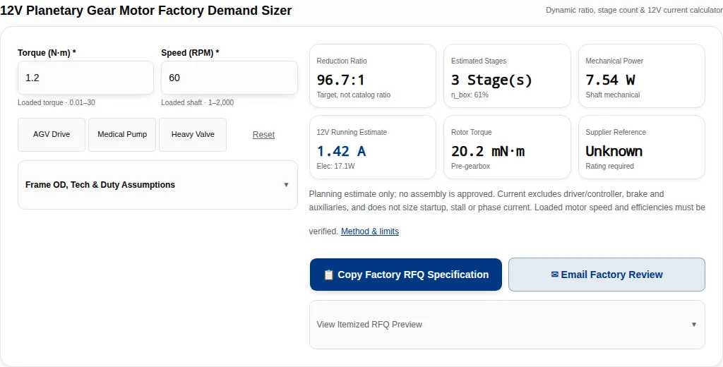
12V Planetary Gear Motor Factory Demand Sizer
Dynamic ratio, stage count & 12V current calculator96.7:1
Target, not catalog ratio3 Stage(s)
η_box: 61%7.54 W
Shaft mechanical1.42 A
Elec: 17.1W20.2 mN·m
Pre-gearboxUnknown
Rating requiredPlanning estimate only; no assembly is approved. Current excludes driver/controller, brake and auxiliaries, and does not size startup, stall or phase current. Loaded motor speed and efficiencies must be verified. Method & limits
View Itemized RFQ Preview▼
Published · Sources reviewed · Published by Micro Planetary Motor
Evidence scope: publisher abstracts and catalog entries checked on the review date, including IEC 60034-1:2026, ISO 1328-1:2013, ISO 281:2007 and ISO 3744:2025. These sources describe methods; they do not verify MPM equipment, certifications or product ratings. Calculations and worked examples use declared assumptions. No measured life, thermal, acoustic or customer-case data is published here.
Four Critical Decisions Before Approving a Factory Gearmotor
When sourcing 12V DC planetary gear motors directly from a manufacturing plant, design engineers and procurement teams must evaluate beyond catalog headline numbers. Review the four essential engineering gates below:
1. Specify the loaded operating point
Torque and loaded speed determine shaft power. Current also depends on assumed motor and stage efficiencies. The sizer estimates demand; it cannot approve a motor or predict startup current.
Related method / evidence scope →2. Verify the manufacturing scope
Ask which winding, gearmaking, assembly and test processes are in-house or subcontracted. A quality-system reference does not establish equipment ownership, certification or a price advantage.
Related method / evidence scope →3. Separate torque from bearing capacity
A diameter or gear ratio is not a load rating. Obtain the exact assembly torque limits and shaft-load conditions. Bearing fatigue life also depends on speed, lubrication and contamination.
Related method / evidence scope →4. Agree sample acceptance before production
Recommended procurement gate: sign off drawings, loaded performance, mounting-specific thermal results and a documented inspection plan before committing volume tooling.
Related method / evidence scope →Reduction Method, Assumptions & 12V Running Demand
A coaxial planetary gearhead distributes torque across three or four planet gears revolving inside a stationary internal ring gear. This coaxial architecture yields high volumetric torque density in miniature frame diameters (Ø10mm to Ø36mm) with model-dependent load sharing. External shaft loads still require a separate bearing check.
Fixed ring, sun input, carrier output
Governing Engineering Formulas:
- Reduction Ratio:
i_total = N_motor_loaded / N_output_loaded; i_stage = 1 + Z_ring/Z_sun - Mechanical Output Power:
P_mech (W) = Torque (N·m) × 2π × RPM / 60 - Cumulative Gearbox Efficiency:
η_gearbox = (η_stage)^N_stages - 12V Operating Current:
I (A) = P_mech / (12.0V × η_motor × η_gearbox)
From a demand estimate to measured performance
Efficiency Sensitivity Under Different Operational Assumptions
Efficiency varies significantly with stage count, lubricant viscosity at cold temperatures, and base motor electromagnetic design. Compare the sensitivity scenarios below:
Scroll the comparison horizontally, or focus it and use the arrow keys.
| Parameter / Topic | Known / Assumed / Unconfirmed | Factory Verification & Action |
|---|---|---|
| Baseline: 1.2 N·m, 60 RPM; loaded motor 5,800 RPM | Assumptions: motor 72%, each stage 85%; estimated 3 stages, ratio 96.67:1. Gearbox 61.41%, system 44.22%. | Calculated: 7.54 W shaft, 17.05 W motor input, 1.42 A at 12V. Excludes controller and auxiliaries; not a supply rating. |
| High reduction: 2.0 N·m, 15 RPM; loaded motor 5,800 RPM | Assumptions: motor 70%, stage 82%; estimated 4 stages, ratio 386.67:1. Gearbox 45.21%, system 31.65%. | Calculated: 3.14 W shaft, 9.93 W motor input, 0.83 A at 12V. Lower running power does not establish startup or holding capability. |
| Brushed example: 0.4 N·m, 80 RPM; loaded motor 6,800 RPM | Assumptions: motor 60%, stage 85%; estimated 3 stages, ratio 85:1. Gearbox 61.41%, system 36.85%. | Calculated: 3.35 W shaft, 9.09 W motor input, 0.76 A at 12V. Frame, cooling and brush life remain unverified. |
Worked OEM Scenarios: Assumptions, Calculations & Validation
These four hypothetical examples demonstrate the method. They are not customer installations, approved configurations or bench-test results. The three presets reproduce the wheel, pump and damper examples. The S2 example uses the same running-power method; the sizer does not provide an S2 duty rating. Reproduce the stated loaded speeds and efficiencies, then obtain supplier validation:
Worked example: Warehouse wheel drive
Hypothetical planning scenario, not a customer installation or measured test.
Engineering Inputs & Load Constraints:
- • Voltage: 12.0V nominal assumption; supply window to confirm
- • Target Load: 1.8 N·m at 55 RPM loaded
- • Duty Cycle: S1 continuous target
- • Ambient: To specify; no thermal model supplied
- • Radial Overhang: To specify with load position and shock factor
Derived Kinematic Calculations:
- • Ratio & Stages: 5,200 loaded motor RPM / 55 output RPM = 94.55:1; 3 estimated stages under the 5.5:1/stage heuristic.
- • Power & Current: Assumed motor η 75%, each stage η 85%. Calculated shaft 10.37 W, motor input 22.51 W, 1.88 A at 12V; excludes controller, startup and auxiliaries.
- • Thermal Headroom: Unknown; winding, mounting and ambient data are required.
Direct Factory Customization:
- • Motor & Gearbox: Candidate technology and envelope must be confirmed by the supplier.
- • Gear Metallurgy: Request grade and geometry-based load rating; no material choice is pre-approved.
- • Bearing System: Request bearing layout, load ratings and shaft deflection check.
- • Feedback & Sealing: Agree controller, feedback, sealing and brake needs in the RFQ.
Evidence Status & Next Validation:
No bench test or life result is claimed. Next step: Request shaft-load limits at the actual wheel offset, endurance data and controller current limits.
Worked example: Quiet pump drive
Hypothetical planning scenario, not a customer installation or measured test.
Engineering Inputs & Load Constraints:
- • Voltage: 12.0V nominal assumption; supply window to confirm
- • Target Load: 0.25 N·m at 80 RPM loaded
- • Duty Cycle: S1 continuous target
- • Ambient: To specify; no thermal model supplied
- • Radial Overhang: To specify with load position and shock factor
Derived Kinematic Calculations:
- • Ratio & Stages: 6,400 loaded motor RPM / 80 output RPM = 80.00:1; 3 estimated stages under the 5.5:1/stage heuristic.
- • Power & Current: Assumed motor η 78%, each stage η 88%. Calculated shaft 2.09 W, motor input 3.94 W, 0.33 A at 12V; excludes controller, startup and auxiliaries.
- • Thermal Headroom: Unknown; winding, mounting and ambient data are required.
Direct Factory Customization:
- • Motor & Gearbox: Candidate technology and envelope must be confirmed by the supplier.
- • Gear Metallurgy: Request grade and geometry-based load rating; no material choice is pre-approved.
- • Bearing System: Request bearing layout, load ratings and shaft deflection check.
- • Feedback & Sealing: Agree controller, feedback, sealing and brake needs in the RFQ.
Evidence Status & Next Validation:
No bench test or life result is claimed. Next step: Measure flow ripple, temperature and acoustic output in the final assembly; medical use needs separate system validation.
Worked example: Intermittent damper
Hypothetical planning scenario, not a customer installation or measured test.
Engineering Inputs & Load Constraints:
- • Voltage: 12.0V nominal assumption; supply window to confirm
- • Target Load: 2.0 N·m at 15 RPM loaded
- • Duty Cycle: S3 target; cycle timing to define
- • Ambient: To specify; no thermal model supplied
- • Radial Overhang: To specify with load position and shock factor
Derived Kinematic Calculations:
- • Ratio & Stages: 5,800 loaded motor RPM / 15 output RPM = 386.67:1; 4 estimated stages under the 5.5:1/stage heuristic.
- • Power & Current: Assumed motor η 70%, each stage η 82%. Calculated shaft 3.14 W, motor input 9.93 W, 0.83 A at 12V; excludes controller, startup and auxiliaries.
- • Thermal Headroom: Unknown; winding, mounting and ambient data are required.
Direct Factory Customization:
- • Motor & Gearbox: Candidate technology and envelope must be confirmed by the supplier.
- • Gear Metallurgy: Request grade and geometry-based load rating; no material choice is pre-approved.
- • Bearing System: Request bearing layout, load ratings and shaft deflection check.
- • Feedback & Sealing: Agree controller, feedback, sealing and brake needs in the RFQ.
Evidence Status & Next Validation:
No bench test or life result is claimed. Next step: Confirm on/off timing, stall protection and holding brake rating; safety-critical functions need an application-specific assessment.
Worked example: Short-time fastener rundown
Hypothetical planning scenario, not a customer installation or measured test.
Engineering Inputs & Load Constraints:
- • Voltage: 12.0V nominal assumption; supply window to confirm
- • Target Load: 0.4 N·m at 300 RPM loaded
- • Duty Cycle: S2 target; duration to define
- • Ambient: To specify; no thermal model supplied
- • Radial Overhang: To specify with load position and shock factor
Derived Kinematic Calculations:
- • Ratio & Stages: 9,000 loaded motor RPM / 300 output RPM = 30.00:1; 2 estimated stages under the 5.5:1/stage heuristic.
- • Power & Current: Assumed motor η 78%, each stage η 85%. Calculated shaft 12.57 W, motor input 22.30 W, 1.86 A at 12V; excludes controller, startup and auxiliaries.
- • Thermal Headroom: Unknown; winding, mounting and ambient data are required.
Direct Factory Customization:
- • Motor & Gearbox: Candidate technology and envelope must be confirmed by the supplier.
- • Gear Metallurgy: Request grade and geometry-based load rating; no material choice is pre-approved.
- • Bearing System: Request bearing layout, load ratings and shaft deflection check.
- • Feedback & Sealing: Agree controller, feedback, sealing and brake needs in the RFQ.
Evidence Status & Next Validation:
No bench test or life result is claimed. Next step: Specify a clutch and current cutoff; validate seating torque and repeated cycles before selecting the gearhead.
Planetary Gearhead Metallurgy, Tooth Strength & Wear Life Analysis
The structural limits of miniature planetary gearboxes are governed by two distinct fatigue phenomena: tooth root bending fatigue (cyclic bending tension at the tooth root fillet) and flank surface contact fatigue (Hertzian rolling-sliding contact shear). Material selection determines torque limits, acoustic behavior, and shock resistance.
Three separate tooth failure checks
MPIF Standard 35 supports material specification; geometry and process-specific tooth ratings are still required. No universal material fatigue limit or torque capacity has been verified here. Use the checklist below to request supporting data:
Scroll the comparison horizontally, or focus it and use the arrow keys.
| Parameter / Topic | Known / Assumed / Unconfirmed | Factory Verification & Action |
|---|---|---|
| POM input-stage candidate | Polymer may be considered where noise and low inertia matter; grade, temperature and geometry change behavior. | No universal dBA reduction or torque rating is established. Request creep, wear and shock validation at the actual load. |
| Press-and-sinter steel candidate | MPIF Standard 35 covers material specification. Grade, density, process and heat treatment must be agreed. | Request grade-specific certificates and geometry-based tooth rating. A material tensile value is not gearbox torque capacity. |
| Sinter-hardened steel candidate | Density and heat treatment affect strength and dimensional control. No verified fatigue limit is published here. | Compare tooth geometry, porosity, hardness and supplier fatigue evidence instead of relying on a material name. |
| Cut / case-hardened steel candidate | Can be evaluated for concentrated loads; process choice affects cost and distortion. | Ask for case depth, core properties, finishing, backlash and shock tests. Do not treat 20CrMnTi and AISI 8620 as interchangeable specifications. |
Direct Factory Manufacturing Capabilities & Equipment Checklist
Ask which operations are performed in-house and which are outsourced. Neither route establishes quality by itself. Review these six process and evidence checkpoints:
Manufacturing evidence to request
Scroll the comparison horizontally, or focus it and use the arrow keys.
| Parameter / Topic | Known / Assumed / Unconfirmed | Factory Verification & Action |
|---|---|---|
| Gearmaking route | Hobbing, press-and-sinter or sourced gearsets are possible routes; ownership is unverified. | Request the process flow, subcontractor controls and model-specific tooth inspection report (ISO 1328-1). |
| Winding and electrical assembly | Winding construction and insulation depend on the selected motor. | Request resistance, insulation test method, winding revision and process traceability. |
| Shaft and flange manufacture | Required tolerances come from the mating assembly, not a universal factory capability. | Sign a drawing with datum, runout, fits and inspection method; ask who machines each feature. |
| Loaded performance testing | No model-specific dynamometer report is published on this page. | Request torque, loaded speed, current, voltage and mounting conditions at your operating point. |
| Noise and vibration testing | No measured noise or vibration benchmark is available here. | Agree fixture, load, speed, measurement quantity, microphone positions and background correction. |
| Assembly and lubrication | Cleanliness, lubricant and sealing requirements are application-specific. | Confirm grease compatibility, dosing, temperature limits and assembly controls; do not infer a cleanroom or IP rating. |
Need a factory engineering audit report?
Request available process records, subcontractor controls and a facility walkthrough; availability and scope need confirmation.
Thermal Dissipation Dynamics, Insulation Classes & Duty Derating (IEC 60034-1)
In enclosed planetary gearboxes, thermal equilibrium occurs when heat generated by armature copper losses (I²R), iron core losses, and gear mesh friction equals heat conducted through the mounting face into the machine chassis. The actual installation determines the allowable thermal load:
Thermal balance depends on the installation
IEC 60034-1:2026 is the rating/performance reference. Agree the applicable thermal test and component limits with the supplier. Continuous, short-time and intermittent ratings are not interchangeable; no fixed torque uplift follows from selecting S3:
Scroll the comparison horizontally, or focus it and use the arrow keys.
| Parameter / Topic | Known / Assumed / Unconfirmed | Factory Verification & Action |
|---|---|---|
| S1 continuous | Operate long enough to reach thermal equilibrium under the specified mounting and ambient. | Use the supplier continuous envelope; motor, magnets, grease, seals and electronics may set different limits. |
| Higher ambient / sealed enclosure | Less thermal headroom may require reduced continuous load. No universal derating factor is known. | Test the final enclosure and mounting. Insulation class alone does not establish allowable surface temperature or assembly life. |
| S2 short-time | A specified running period is followed by sufficient cooling. Duration must be declared. | Obtain an approved torque/time envelope; do not apply a fixed percentage increase over S1. |
| S3 intermittent periodic | For an illustrative 25% cycle, 2.5 min on and 7.5 min off share the same fraction as 15 s on and 45 s off, but thermal behavior can differ. | Supply cycle length, starts, peak loads and inertia. The sizer does not increase permissible torque for S3. |
| High-temperature alternative | A higher insulation class alone does not qualify the magnet, lubricant, polymer or bearing. | Ask for whole-assembly validation or consider relocating the drive / improving cooling. |
Output Shaft Cantilever Loading & Bearing Life (ISO 281:2007)
Pulleys, pinions and direct-drive wheels can apply overhung loads. Resolve the reactions using the actual bearing centers, then check shaft strength, deflection, bearing static capacity and fatigue life. Bearing count alone does not establish capacity.
Resolve load from the bearing centers
Simplified Bearing Reactions & ISO 281 Fatigue-Life Method:
- Front Bearing Reaction Load:
Rf = Fr × (1 + L / B)where L is measured from the front bearing center and B is the span between ideal supports. This purely radial statics model excludes preload and axial load; Rf is not automatically the equivalent dynamic bearing load P. - Bearing Rating Life L10h:
L10h = (10^6 / (60 × N)) × (C / P)^p = (16,667 / N) × (C / P)^p(p = 3 for ball bearings; p = 10/3 for roller bearings). Basic L10 corresponds to 90% fatigue reliability, not total gearbox life; lubrication, wear and contamination need separate consideration.
Overhang sensitivity: a reproducible statics example
Always position the driving pulley or pinion as close to the front mounting spigot as possible (minimizing cantilever distance L). For high radial loads, ask the supplier about a rated bearing arrangement or consider an independent external support bearing.
Related source and limits →Acoustic Noise Control & Vibration Attenuation Engineering (ISO 3744)
Acoustic noise in planetary gearmotors originates primarily from the high-speed input sun gear engaging the first stage planets. Gear tooth deflection, pitch transmission errors (ISO 1328-1), and resonant cavity acoustic amplification define the radiated sound signature.
Acoustic evidence: define, measure, compare
No measured acoustic spectrum or fixed material noise reduction is available here. Compare candidate assemblies under the same loaded speed, mounting and test method; document uncertainty:
Scroll the comparison horizontally, or focus it and use the arrow keys.
| Parameter / Topic | Known / Assumed / Unconfirmed | Factory Verification & Action |
|---|---|---|
| Sound pressure at a stated position | Model-specific LpA is unknown. A single reading is not sound power. | Compare at identical load, RPM, mounting, microphone position and background conditions. |
| Sound power by measurement surface | ISO 3744:2025 provides an engineering method using multiple pressure measurements. | Request LWA, measurement-surface geometry, corrections and uncertainty; do not label a 30 cm SPL reading as a complete ISO 3744 test. |
| Material / stage comparison | No measured spectrum or guaranteed material ranking is available here. | Run an A/B test at equal output duty; inspect mesh bands and controller excitation as well as overall dBA. |
| Vibration and application fit | A universal ISO 10816 severity class is not established for these miniature drives. | Agree sensor placement, fixture, units, frequency bands and application-specific acceptance limits. |
Factory Quality Testing Standards & Verification Gates
Agree the inspection plan, acceptance values and applicable standards for the exact use case. The following methods do not establish certification or guarantee service life:
Scroll the comparison horizontally, or focus it and use the arrow keys.
| Parameter / Topic | Known / Assumed / Unconfirmed | Factory Verification & Action |
|---|---|---|
| Continuous thermal validation | IEC 60034-1 provides a rating/performance framework; it does not assign a rating to this assembly. | Record winding method, ambient, enclosure, heat sink, supply and steady operating temperatures. |
| Peak and shock torque | Allowable peak duration and cycles are unknown until the supplier rates the assembly. | Ask for peak envelope and test procedure. Do not hold a motor at stall to establish continuous operation. |
| Backlash and accuracy | ISO 1328-1 concerns individual gear-flank tolerances, not assembled gearbox backlash. | Specify output backlash test torque, direction, temperature and allowed change over life. |
| Shaft and bearing life | ISO 281 addresses bearing fatigue life; the gearbox and shaft have additional limits. | Obtain bearing C rating, equivalent load method, load reference position and speed; check static/shock loads separately. |
| Corrosion validation | ASTM B117 describes salt-fog apparatus operation; duration and acceptance require a separate agreement. | Specify substrate/coating, exposure, failure criteria and post-test function. Do not convert fog hours into field life. |
Factory Customization Scope & Tooling NRE Tiers
Use these options as RFQ requests. Manufacturing feasibility, NRE, tolerances and availability require supplier confirmation:
Scroll the comparison horizontally, or focus it and use the arrow keys.
| Parameter / Topic | Known / Assumed / Unconfirmed | Factory Verification & Action |
|---|---|---|
| Shaft geometry | D-flat, stepped shaft, keyway and cross-hole are candidate requests; availability is unconfirmed. | Provide a dimensioned drawing, mating loads and tolerance stack; request tooling and inspection cost. |
| Mounting interface | Pilot and screw pattern must match the customer assembly. | Check screw engagement, bearing clearance, concentricity and STEP interference before sign-off. |
| 12V winding | No-load speed and loaded motor speed differ. | Request torque-speed-current data over the actual supply window and at temperature. |
| Encoder and Hall signals | Resolution, shaft location and electrical interface must be specified together. | State counts vs quadrature edges, logic voltage, output type, cable and controller compatibility. |
| Holding brake | A brake is a candidate addition; gear reduction does not guarantee self-locking. | Confirm static hold, response, release current, wear and emergency duty; validate any fail-safe requirement separately. |
| Environmental sealing | IP capability and seal drag are unknown for the selected shaft/enclosure. | Request an applicable ingress test report and verify cold startup after sealing. |
Procurement Comparison: Direct Factory vs Broker vs Catalog Distributor
Selecting the right supply channel directly impacts unit cost, drawing revision speed, and mass production consistency. Review the three commercial channels:
Scroll the comparison horizontally, or focus it and use the arrow keys.
| Parameter / Topic | Known / Assumed / Unconfirmed | Factory Verification & Action |
|---|---|---|
| Direct manufacturer | May offer direct access to drawing and production changes. In-house scope still needs verification. | Compare engineering access, traceability and total landed cost; do not assume lower prices or zero NRE. |
| Trading / sourcing company | May coordinate multiple factories, consolidate shipments and handle communication. | Name the actual manufacturer, control revisions and agree warranty/inspection responsibility. |
| Catalog distributor | May offer local stock, low sample quantities and published specifications. | Check authorized status, stock, customization options and repeat-order availability; compare total cost. |
Commercial Terms, Lead Times, and Production MOQ Tiers
Plan sample, pilot and annual volumes separately. These quantities are illustrative; MOQ, lead time, pricing and test coverage require a dated written quotation:
Scroll the comparison horizontally, or focus it and use the arrow keys.
| Parameter / Topic | Known / Assumed / Unconfirmed | Factory Verification & Action |
|---|---|---|
| Sample plan: 5–20 pcs (illustrative) | Use samples to validate geometry and loaded performance. MOQ and price are unconfirmed. | Ask for stock/tooling status, sample lead time, test scope and courier cost in a written quote. |
| Pilot plan: 100–500 pcs (illustrative) | Use a pilot to evaluate process repeatability; this is not a factory MOQ commitment. | Agree FAI, sampling, lot traceability, change control, fixture NRE and acceptance before release. |
| Annual plan: 1,000–50,000 pcs (illustrative) | Capacity, payment, Incoterm and repeat-order delivery are not established by this page. | Quote volume breaks, tooling ownership, warranty, packing, import costs and delivery milestones. |
Procurement Risks & Mitigation Strategies
Avoid common traps when sourcing 12V micro gear motors:
Scroll the comparison horizontally, or focus it and use the arrow keys.
| Parameter / Topic | Known / Assumed / Unconfirmed | Factory Verification & Action |
|---|---|---|
| Misuse: confusing calculated demand with a rating | An assumed efficiency or diameter cannot establish safe continuous/peak torque. | Request the exact motor/gearhead/controller limits and test the final mounting. |
| Cost: tooling and logistics omitted | Custom shafts, fixtures, inspection, shipping and duties can change the total cost. | Request itemized NRE, tooling ownership, landed-cost assumptions and acceptance terms; compare stock alternatives. |
| Mismatch: duty and enclosure | An open-bench result may not transfer to a sealed hot enclosure or high-start cycle. | Test the actual cycle/ambient. Consider a larger drive, better cooling or external bearings. |
| Shock and backdrive | Hard stops and external wheel/valve loads can exceed the running torque. | Define peak duration and cycles, clutch/brake strategy and an independent support bearing where needed. |
Frequently Asked Questions (Factory & Engineering FAQs)
Comprehensive answers to the top engineering, auditing, and commercial questions encountered by OEM procurement teams:
1. How can I verify a direct motor factory?▼
2. What is the MOQ?▼
3. What lead time should I use?▼
4. Should I choose brushed, BLDC or coreless?▼
5. Do gear materials establish torque or noise?▼
6. Can I request a custom shaft?▼
7. Does this page prove ISO or IATF certification?▼
8. Does ISO 1328-1 specify assembled backlash?▼
9. How should I validate a sealed motor enclosure?▼
10. What encoder information belongs in the RFQ?▼
11. Does a low estimated current mean easy startup?▼
12. Which drawings and inspection reports should I request?▼
13. What payment and shipping terms apply?▼
14. Is ISO 3744 a single 30 cm dBA test?▼
15. Does a planetary gearhead prevent back-driving?▼
16. Can I use peak torque just by selecting S3?▼
17. How do I estimate bearing life with an overhung load?▼
18. How do I start a factory review?▼
Engineering Standards & Reference Citations
These publisher records establish the scope of the cited methods. The running-demand model and hypothetical examples are explained above; none of these links establishes a supplier rating or certification:
IEC 60034-1:2026 — Rating and performance ↗
Scope / Limitation: Publisher scope and edition verified 2026-11-10; replaces the 2022 edition. Rating framework only; confirm applicable clauses and test limits for the exact motor/drive.
ISO 1328-1:2013 — Gear flank tolerance classification ↗
Scope / Limitation: Publisher abstract verified 2026-11-10. Covers individual cylindrical involute gear flank tolerances; does not provide assembled torque, efficiency or backlash ratings.
MPIF Standard 35 — Materials standards ↗
Scope / Limitation: Publisher standards index checked 2026-11-10. Use the appropriate process/material specification and agree grade/properties. No grade-specific gear fatigue or torque values have been verified here.
ISO 281:2007 — Bearing dynamic ratings and rating life ↗
Scope / Limitation: Publisher abstract checked 2026-11-10. Basic fatigue rating life uses 90% reliability; wear, corrosion and electrical erosion are outside its life model.
ANSI/AGMA 2101-E25 — Involute gear tooth rating ↗
Scope / Limitation: Publisher catalog checked 2026-11-10; its 2026 catalog lists 2001-D04 as replaced by 2101-E25. Tooth rating requires geometry and rating factors; no assembly approval is inferred.
ISO 3744:2025 — Sound power using sound pressure ↗
Scope / Limitation: Publisher abstract checked 2026-11-10. Replaces the 2010 edition. A measurement-surface method, not a universal fixed-distance sound-pressure limit.
ISO 9001 — Quality management requirements ↗
Scope / Limitation: ISO committee overview checked 2026-11-10. Quality-management context only; neither this link nor this guide establishes a supplier certificate, Cpk target or manufacturing scope.
ASTM B117-26 — Operating salt spray apparatus ↗
Scope / Limitation: Publisher overview checked 2026-11-10. Exposure duration and acceptance are to be agreed; no 24–96 hour universal acceptance requirement or field-life prediction is claimed.
Submit Your 12V Planetary Gear Motor Factory RFQ
Send your mechanical load, loaded speed, operating duty cycle, envelope drawing, and batch quantity to our factory application engineering team. Request model availability, revision-controlled drawings, test scope, lead time and an itemized quotation.
Inquiry Email
Include OD/length, voltage, torque, loaded speed, ratio, drawings, quantity, and destination.
Instant Chat
WhatsApp Engineering Support
Fast channel for clarifying specs, drawings, and sample timing.