
Wide-Temperature Lubrication in Micro Planetary Gear Motors: Cold-Start Torque Surges, High-Temp Oil Bleed, Synthetic PAO vs. PFPE Selection, and Fill Ratio Standards
Select wide-temperature lubrication for micro planetary gear motors: compare PAO and PFPE, assess cold-start drag and oil bleed, and prepare an RFQ checklist.
Wide-temperature lubrication in micro planetary gear motors requires a matched grease, gear train, motor, and drive supply. For an actuator specified at -40°C to +125°C, neither a lubricant temperature label nor the words "synthetic grease" establish that the assembled device will start cold, retain lubricant when hot, or meet its service-life target.
Selection answer: Start with a supplier-supported PAO formulation for a conventional outdoor actuator. Consider a specific PFPE grade when chemical exposure, volatility, or thermal requirements justify it. Approve either only after checking material compatibility, assembled cold-start current and torque, hot migration, and controlled fill mass. There is no universal micro-gearhead fill percentage or grease-test torque limit.
Reviewed: November 6, 2026. Scope: This English-language guide supports global OEM engineering and procurement of approximately 6–32 mm planetary gearmotors. Temperature examples describe qualification scenarios, not ratings of our products. The worked calculations below use hypothetical inputs; they are not measured motor results, customer case studies, medical approvals, or lifetime guarantees. Confirm application-specific requirements with the motor and lubricant suppliers.
If your RFQ already names a temperature range, request a lubrication application review with the cold-start voltage, load, duty cycle, gear materials, and required life.
1. Physics of Low-Temperature Viscous Drag and Cold-Start Torque Surges
A small motor has a limited torque reserve. As grease cools, base-oil viscosity and the grease's resistance to deformation can increase. Bearing friction, seal drag, gear contacts, and lubricant displacement then compete with the load for the available starting torque. A start failure may appear as a driver current-limit event, an incomplete stroke, or a stalled rotor. Lubrication is one possible cause; a cold battery or mechanical interference can produce similar symptoms.
1.1 Viscosity Is a Screening Input, Not a Starting-Torque Prediction
The ASTM D341/Walther relationship describes an oil's viscosity-temperature behavior within its applicable range. It does not turn a base-oil viscosity into a grease breakaway torque. Extrapolating far below available viscosity measurements can be misleading, particularly near low-temperature flow limits. Grease is also non-Newtonian: thickener structure, shear history, and dwell time matter.
Ask for the actual formulation's viscosity data and low-temperature test conditions. Do not assume that all ISO VG 100 mineral oils increase viscosity by a fixed multiplier at -40°C, or that every PFPE grease flows better than every PAO grease. A product's useful temperature range also does not establish acceptable drag in your motor.
1.2 Keep Every Torque Term on the Same Shaft
For a preliminary motor-shaft budget, use the following relationship. It is an engineering screening model, not a validated grease constitutive model:
T_required,motor = T_load,output / ratio
                 + T_losses,motor + T_acceleration,motor
T_available,motor = Kt × permitted motor current
Here, loss torque includes all grease, gear, bearing, and seal resistance referred to the motor shaft, including load-dependent friction. Obtain or bound those losses at the actual cold condition. The load term uses the ideal ratio; do not also divide by an efficiency that already includes the same losses. If measured assembly data already includes them, do not add them again. A room-temperature running-efficiency figure may not apply at breakaway, and a viscous running model proportional to speed cannot predict grease yield resistance at zero speed.
Hypothetical example: Suppose the output load is 60 mN·m and the reduction ratio is 100:1. The ideal reflected load is 60 / 100 = 0.60 mN·m. If hypothetical total cold loss torque is 1.5 mN·m, the preliminary demand is 2.1 mN·m before acceleration and design margin. With Kt = 5 mN·m/A and a permitted current of 0.40 A, available torque is only 2.0 mN·m. This scenario fails the preliminary budget.
Raising the current limit is not automatic approval: verify winding heating, driver peak duration, battery sag, wiring, and gear peak-torque limits. For BLDC drives, align the current definition with the supplier's torque constant and commutation method. A bench supply at nominal voltage does not reproduce a cold battery's terminal voltage.
1.3 What ASTM D1478 Can and Cannot Establish
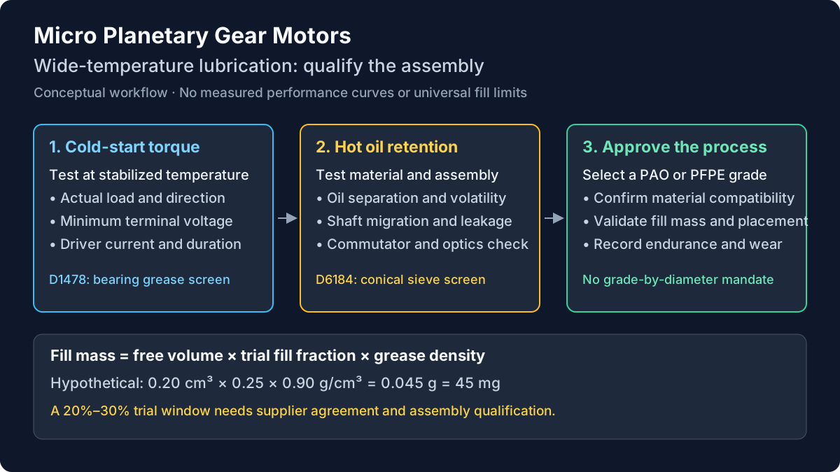
ASTM D1478 concerns low-temperature torque of ball-bearing greases. It can support formulation comparison when the bearing, grease preparation, temperature, and procedure are comparable. Its result is not the starting torque of a planetary gearmotor, and a bearing-test value cannot be compared directly with your motor's stall torque.
Request the report, stated standard edition, test temperature, units, and starting/running results. Establish the separate assembly acceptance limit from the available motor torque and application load. There is no universal 15 mN·m pass limit or 50 mN·m failure threshold for motors below 16 mm. In the actual assembly, verify temperature stabilization, start direction, dwell, load, supply voltage, and driver settings before accepting a formulation.
2. High-Temperature Degradation: Oil Separation, Evaporation, and Commutator Creep
At elevated temperature, lubricant retention depends on the complete grease formulation, housing, seals, orientation, and thermal duty. Some release of base oil is necessary for lubrication; a lower separation percentage is not automatically better if the contact becomes starved. Excessive separation or evaporation can nevertheless reduce the oil available to the mesh or contaminate adjacent components.
2.1 Separate Static Oil Separation from Assembly Migration
ASTM D6184 addresses oil separation from lubricating grease by the conical sieve method. Use it as a comparative material test with the temperature, duration, and procedure recorded. A result from one condition should not be compared with another without qualification. The following expression describes the reported mass fraction, not a time-normalized bleed rate:
Oil separation (%) = collected separated oil mass / initial grease mass × 100A sieve result does not predict the amount of oil reaching a motor commutator. Run a separate hot-storage and powered thermal-cycle test on the intended gearmotor. Inspect the tooth contacts, shaft path, motor chamber, and sensor area. Record current, speed, leakage, and feedback behavior before and after the exposure. Define what counts as contamination before testing begins.
Oil on a brushed motor's contact system can alter commutation and brush wear; contamination on an optical code wheel can interfere with feedback. These are risks to investigate, not proof that every oil-bleed event causes immediate motor failure. Magnetic feedback is not optically blinded, although its electronics, adhesives, and mechanical clearances still need contamination review. Do not assign a brush-life reduction or failure time without measured evidence.
2.2 Anti-Creep Barriers Are One Design Option
An epilame treatment can reduce surface wetting and oil creep in a qualified design. It is not a permanent seal or a guarantee of zero migration. Treatment chemistry, cleaning, coverage, wear, and compatibility with the actual lubricant affect performance. Fluorinated oils may behave differently from hydrocarbon oils on a chosen treatment.
Consider housing separation, shaft geometry, controlled lubricant placement, seals, or a validated coating as alternatives or combined measures. Request the supplier's treatment specification and thermal-cycle evidence. A UV inspection is useful only when the selected material contains a suitable tracer and the inspection process has been validated.
3. Base Oil Chemistry and Thickener Matrix: PAO vs. PFPE Selection
The decision matrix below is a shortlist, not a datasheet. Temperature limits, viscosity, separation, compatibility, and cost belong to the named finished formulation. Do not turn a chemical family into an approved bill-of-materials entry.
| Candidate family | Reason to shortlist | Main qualification concern | Evidence to request |
|---|---|---|---|
| Mineral-oil grease | Cost-sensitive service within a demonstrated envelope | Cold drag and thermal aging depend on grade and formulation | Viscosity data, cold-start results, hot retention |
| PAO grease | Candidate for a broad outdoor temperature window | Thickener, additives, viscosity, and seals still determine suitability | Exact grade, compatibility statement, assembly tests |
| PFPE/PTFE grease | Chemical resistance, low volatility, or demanding thermal service | Grade-specific cold behavior, density, cost, and cleaning requirements | Product datasheet, cold torque, contamination-control process |
| Ester-containing grease | Potential thermal and lubrication benefits | Compatibility with the specific polymer, elastomer, and additive package | Stressed-material exposure and supplier approval |
| Silicone grease | Selected sealing or specialized lubrication duties | Electrical-contact contamination and loaded-gear suitability | Explicit motor and lubricant supplier approval |
| PAG grease | Specialized lubrication requirements | Water uptake, material compatibility, and mixing restrictions vary | Formulation-specific compatibility and aging reports |
| Alkylbenzene-containing grease | Specialty formulation requirements | No family-wide micro-gearhead performance assumption is justified | Finished-product data and application qualification |
3.1 PAO Is a Candidate; PFPE Is Not an Automatic Upgrade
For a conventional outdoor actuator, PAO is a reasonable starting candidate when a supplier supports the required operating window. Compare complete formulations at equivalent test conditions rather than relying on viscosity index alone. A low-viscosity grade may reduce drag while changing film formation, noise, leakage, and wear. Ask which trade-off the supplier optimized.
PFPE is worth evaluating when its chemical resistance or volatility properties solve a defined problem. Grade selection remains essential. For example, Chemours' automotive lubricant table lists PFPE grease GPL 204 at -51°C to +179°C with 60 cSt base-oil viscosity at 40°C, while GPL 205 is listed at -36°C to +204°C with 160 cSt. These published ranges do not establish gearmotor cold-start performance, but demonstrate why a family-wide -65°C rating is inappropriate.
Procurement should compare dispensing, cleaning, qualification, and supply costs alongside grease price. Request a quotation for the actual fill mass and process. A universal cost multiplier or cents-per-motor premium would conceal those differences.
3.2 Silicone and Brushed Electrical Contacts
Treat silicone-containing lubricants and nearby silicone materials as a contamination concern in brushed motor designs. Ask the motor supplier to approve the specific material, its location, and exposure conditions. Removing a commutator by choosing BLDC does not establish that silicone grease is suitable for its gears, sensors, or bonding materials. Avoid an unqualified material substitution based only on a wide temperature label.
3.3 Plastic Gear Compatibility Requires the Actual Materials
POM, PEEK, polycarbonate, elastomers, adhesives, and coatings are distinct materials. Neither "all esters attack plastics" nor "all PAO is plastic-neutral" is a sound purchasing rule. Finished greases include additives and may contain blended base oils. A compatibility statement for one resin or unstressed coupon cannot approve every gear material.
Ask for testing on the specified resin grade and elastomer under representative temperature, exposure time, and mechanical stress. Inspect dimensions, cracking, hardness where applicable, and functional performance. Retest after a resin, additive, lubricant, or cleaning-process change. Chemours describes plastic and elastomer compatibility for its Krytox products; that statement is not approval of every material in your assembly.
4. NLGI Consistency Grades and Channeling in Micro Frames
NLGI grade describes grease consistency using worked penetration; it does not specify base-oil viscosity, cold-start torque, or gear diameter. Softer grease may redistribute more readily but can be harder to retain. A stiffer formulation may stay in place while providing adequate oil release. Geometry, speed, temperature, and application method affect the result.
The conventional ranges below help identify consistency. They are not motor-size selection limits; request the supplier's penetration report and method.
| NLGI grade | Worked penetration, 0.1 mm at 25°C | Qualification focus |
|---|---|---|
| 000 | 445–475 | Very fluid: demonstrate containment |
| 00 | 400–430 | Semi-fluid: compare redistribution with leakage |
| 0 | 355–385 | Soft: verify retention through thermal cycles |
| 1 | 310–340 | Compare contact replenishment and starting drag |
| 2 | 265–295 | Verify distribution; do not reject on diameter alone |
| 3 | 220–250 | Require evidence for placement and replenishment |
4.1 Distinguish Channeling from Proven Starvation
Gears can push grease away from their swept path. A channel visible during teardown does not, by itself, prove that the contact ran dry: oil release and residual films may still lubricate it. Correlate grease location with wear, current, noise, and temperature over the intended duty cycle. Conversely, a housing full of grease does not prove that oil reaches every contact.
4.2 Select Consistency by Test
Shortlist grades that the gearhead and grease suppliers consider practical, then vary consistency while controlling formulation differences as far as possible. Evaluate both cold starts and hot retention. There is no general rule mandating NLGI 00 below 12 mm or forbidding NLGI 2 below 24 mm. Record orientation and reversals because they can change distribution in an intermittent actuator.
5. Fill Volume Ratio: Control Mass and Validate the Window
More grease can increase displacement resistance and churning, while too little can leave contacts inadequately supplied. Overfilling may also encourage leakage as the assembly heats. The magnitude depends on the design; fixed efficiency losses, temperature rises, or failure times cannot be assigned without tests.
5.1 Define the Volume Before Setting a Percentage
Define free volume as housing cavity volume minus the volume occupied by the assembled gears, carriers, pins, shafts, and other internal parts. State whether bearing pockets and isolated spaces are included. A percentage of the empty housing is not interchangeable with a percentage of net free volume.
Grease mass (g) = free volume (cm³) × selected fill fraction × density (g/cm³)Hypothetical dispensing example: With 0.20 cm³ free volume, a trial fill fraction of 0.25, and an assumed grease density of 0.90 g/cm³, the dose is 0.20 × 0.25 × 0.90 = 0.045 g, or 45 mg. If a replacement grease's datasheet density were 1.90 g/cm³, the same volume would require 95 mg. Equal masses would therefore not be equal fills.
5.2 Treat 20%–30% as an Experimental Window
The 20%–30% window discussed here is a possible development trial, not an ASTM, ISO, or universal micro-planetary standard. Use it only when the gearhead supplier considers it appropriate. Compare a justified lower, nominal, and upper dose against cold-start current, hot leakage, mesh wear, noise, and life requirements. Some designs need different amounts or localized placement rather than a cavity-wide fill ratio.
5.3 Verify the Dispensing Process
Translate the approved dose into a drawing requirement in milligrams with a tolerance and application locations. Choose dispensing equipment for the actual grease, shot size, and production rate. Confirm delivered mass by weighing representative shots and assembled parts where practical; a machine's nominal repeatability is not proof of process capability.
Record grease batch, storage conditions, nozzle, temperature, calibration, and check frequency. Include controls for trapped air and carryover from previous lubricants. Revalidate when changing grease or equipment. If you need assembly geometry to estimate free volume, request CAD and dimensional data before agreeing to a production dose.
6. Food, Medical, Vacuum, and Cleanroom Boundaries
Special environments require application-specific review beyond a wide-temperature lubricant label. A registration or material test does not certify the complete gearmotor for its end use.
6.1 Food Contact and Medical Use Are Separate Decisions
Where incidental food contact is relevant, request the exact product's current registration, permitted use conditions, and traceability. NSF H1 status does not establish medical-device biocompatibility, suitability for tissue or drug contact, or compatibility with a sterilization process. Medical programs need their own material, cleaning, contamination, and device-level validation. Do not infer approval from a lubricant being described as food-grade.
6.2 Vacuum Outgassing Is a Material Test, Not a Complete Qualification
ASTM E595 addresses total mass loss and collected volatile condensable materials from outgassing in vacuum. Specify the report and project acceptance criteria separately. The test method does not prescribe a PFPE chemistry, establish a motor's operating-temperature range, or guarantee acceptable contamination at a sensitive optical surface.
For vacuum or cleanroom service, define pressure, temperature, exposure time, allowable deposition, particles, and all exposed materials. Assess seals, adhesives, wire insulation, and assembly residues as well as grease. An appropriate material report is an input to assembly qualification, not a replacement for it.
7. Engineering and Procurement Checklist: A Lubrication RFQ Specification
Use this ten-point checklist to turn the discussion into reviewable supplier deliverables. Values must come from the application and qualification plan. The table deliberately separates material tests from assembled-motor acceptance.
| Step | RFQ parameter | Requirement to agree | Verification evidence |
|---|---|---|---|
| 01 | Formulation identity | Manufacturer, grade, revision, substitution control | Datasheet, batch traceability, written change control |
| 02 | Materials | Gear resin, metals, seals, adhesives, cleaning residues | Compatibility statement and representative exposure tests |
| 03 | Thermal envelope | Cold start, hot running, storage, dwell, duty cycle | Stabilized chamber and powered-duty records |
| 04 | Consistency | Named NLGI grade and penetration method | Supplier report plus assembly distribution checks |
| 05 | Oil viscosity | Reported values, units, temperatures, data limitations | Formulation-specific oil data |
| 06 | Cold starting | Minimum terminal voltage, load, current limit, direction, start time | Instrumented assembly test; D1478 only as supplementary material data |
| 07 | Hot retention | Separation test conditions and separate migration limits | D6184 report where relevant; assembly inspection |
| 08 | Fill control | Mass, tolerance, location, free-volume definition | Dispensing calibration and sample mass records |
| 09 | Service performance | Cycles, reversals, load, speed, noise, allowable wear | Agreed endurance protocol and teardown evidence |
| 10 | Special environment | Relevant food, medical, vacuum, or cleanliness requirements | Exact-product documents and application-specific validation |
For a useful qualification sequence, first document baseline current, speed, backlash, and noise at room temperature. Then stabilize the assembly at the cold condition and perform starts in both directions under the worst credible supply and load. Follow with the specified hot duty and storage exposures, then repeat cold starts and inspect for migration and wear. The order matters because prior operation redistributes grease and may change later results.
Agree sample count, lubricant batches, allowable failures, measurement accuracy, and teardown criteria before testing. One successful prototype does not establish production reliability. Retain individual failures rather than reporting only a favorable average. If results differ between formulations, confirm that fill mass, housing, motor lot, and test sequence were comparable before attributing the change to base-oil chemistry.
8. Frequently Asked Questions
Can liquid gear oil replace grease in a micro planetary gearbox?
Only if the design supports oil lubrication and retention. Bushings and small shaft clearances should not be assumed to provide a liquid-tight seal. Semi-fluid grease can also leak, so changing from oil to NLGI 00 is not automatic containment approval. Ask the gearhead supplier which lubricant forms and orientations have been qualified.
Why can a motor pass a laboratory cold start and fail in the field?
Check actual core temperature, soak history, supply voltage at the motor terminals, driver limits, load, and start direction. A timed freezer exposure does not prove thermal equilibrium; establish stabilization with a suitable measurement. Field battery sag or a higher load may remove the torque margin. Repeat the test with recorded conditions before blaming the grease.
Does thicker grease always make a gearbox quieter?
No. Grease can change damping and friction, but the effect depends on gear geometry, speed, housing, temperature, and formulation. Higher consistency and higher base-oil viscosity are different properties. Compare noise under a defined fixture, microphone position, load, and thermal condition, alongside current and wear. Do not promise a fixed decibel reduction without measurements.
Are extreme-pressure additives safe for bronze bushings and plastic gears?
Compatibility depends on the finished formulation and materials. Ask for relevant corrosion and polymer-compatibility evidence rather than banning all sulfur or assuming solid additives are harmless. Additives useful for one steel gear contact may be unsuitable for another component or cleanliness requirement. Approve the complete lubricant against the complete assembly.
What shelf life should purchasing specify?
Request the grease manufacturer's storage guidance and the gearmotor supplier's packaged-assembly storage limit. Record storage temperature, packaging, humidity, orientation, and age. Grease shelf life is not the same as assembled-device storage life. Do not assign universal three-to-five-year PAO life, mineral-grease expiry, or a mandatory run-in duration without supplier evidence.
Can we re-grease a small gearmotor in the field?
Check the service instructions. A crimped or sealed unit may not be designed for disassembly; opening it can disturb gears, seals, and cleanliness. Do not mix PFPE and hydrocarbon greases or change chemistry without an approved cleaning and conversion process. For a non-serviceable assembly, qualify the intended duty and arrange replacement criteria rather than assuming bearing-life calculations establish grease life.
9. Sources and Engineering Standards
These references support material-test terminology and grade-specific comparison. They do not certify our gearmotors or substantiate the hypothetical torque and fill examples. Request the full applicable standard, contractual edition, current datasheet, and actual supplier report before acceptance; the ASTM catalogue links below identify specific editions, not a claim that each is the latest edition.
- ASTM D1478-20 — Low-Temperature Torque of Ball Bearing Greases. ASTM catalogue. Relevant to grease screening in a specified bearing fixture; not an assembled planetary gearmotor torque limit.
- ASTM D6184-17 — Oil Separation from Lubricating Grease (Conical Sieve Method). ASTM catalogue. Relevant to material separation under reported conditions; not a direct commutator-contamination test.
- ASTM E595-15(2021) — Total Mass Loss and Collected Volatile Condensable Materials from Outgassing in a Vacuum Environment. ASTM catalogue. Relevant to material outgassing; project acceptance and complete-assembly qualification are separate.
- Chemours — Krytox lubricant solutions for automotive applications. Manufacturer product table. Shows that PFPE viscosity and useful temperature ranges vary by grade. Manufacturer information is not independent motor validation.
10. Engineering Review and Custom Lubrication Sourcing
Prepare one application brief containing the assembly envelope, gear and seal materials, cold-start voltage, load, duty cycle, maximum internal temperature, life target, cleanliness requirements, and expected order volume. Ask the supplier to identify a candidate formulation, proposed fill mass, available test evidence, and unresolved qualification work. This makes competing proposals comparable without assuming capabilities or compliance that have not been documented.
Request a technical review and quotation to discuss that brief. For mechanical options, review OEM customization or browse micro planetary gear motor products. Confirm available lubrication processes, test conditions, lead time, and acceptance documents in the quotation before ordering qualification samples.
Author

Categories
More Posts
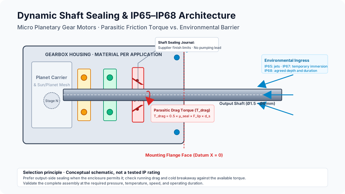
Dynamic Shaft Sealing and IP65 to IP68 Protection in Micro Planetary Gear Motors: Parasitic Drag Torque, Seal Architectures, and Waterproof Actuator Engineering
Specify IP65 to IP68 micro planetary gear motors: compare shaft seals, budget drag torque, assess thermal pumping, and prepare an engineering RFQ checklist.
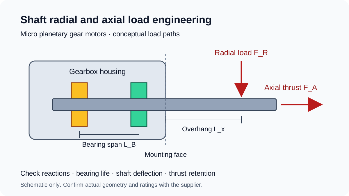
Shaft Radial and Axial Load Engineering in Micro Planetary Gear Motors: Overhung Sizing, Bushings vs. Dual Ball Bearings, and ISO 281 L10h Life
Size micro planetary gear motor shaft loads: calculate overhung reactions, compare bushings and ball bearings, and prepare an RFQ with ISO 281 L10h life inputs.
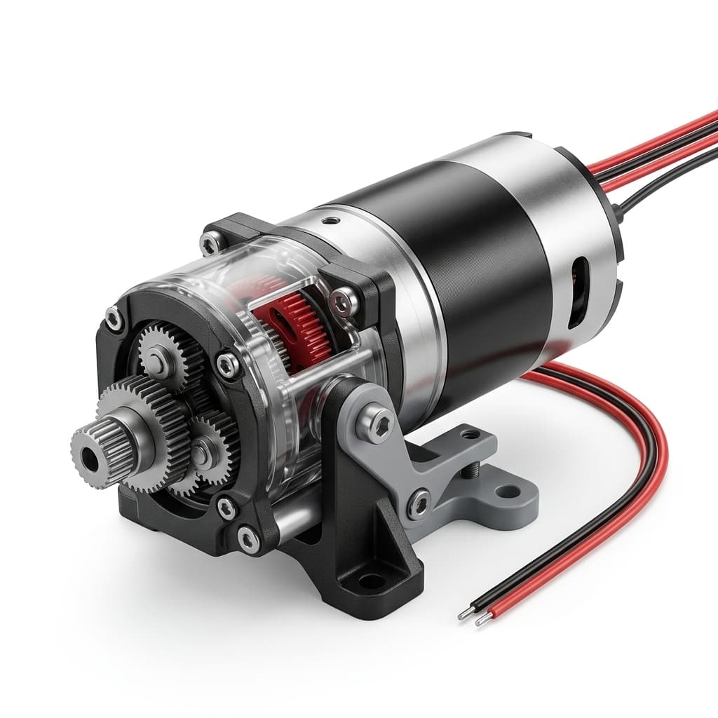
How to Choose the Right Micro Planetary Gear Motor for Your Application
A comprehensive buyer-side engineering guide on sizing, torque requirements, gear materials, and selecting the optimal micro planetary gear motor architecture.