
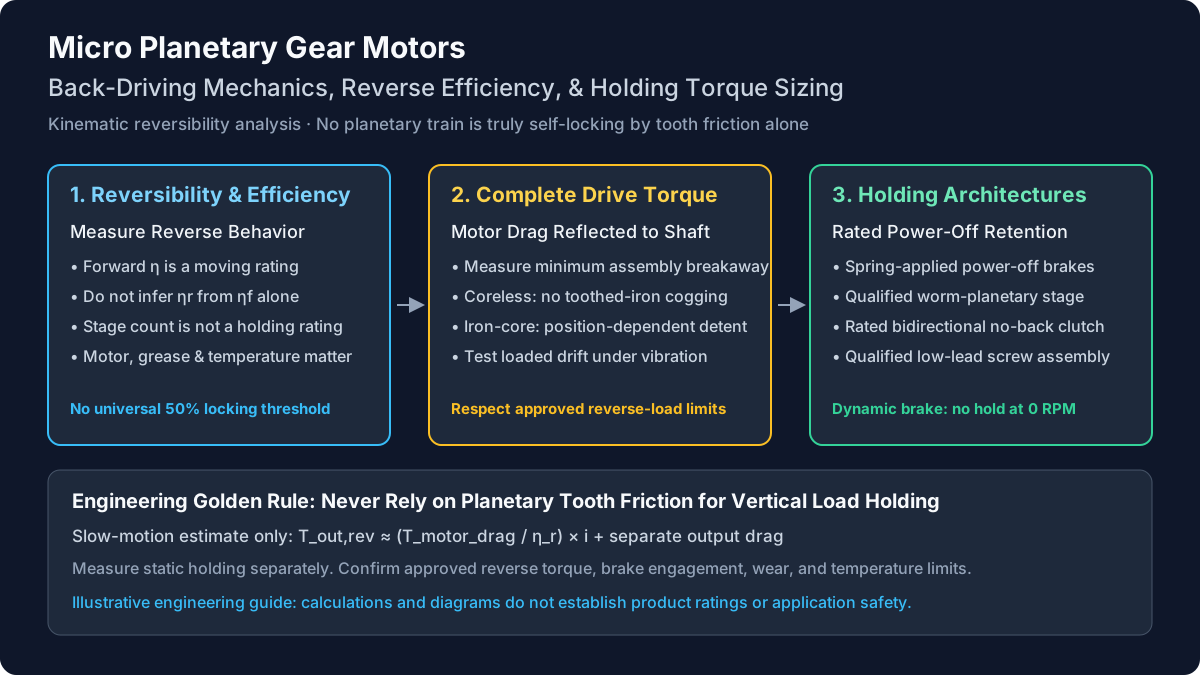
Back-Driving in Micro Planetary Gear Motors: Reversibility Thresholds, Holding Torque Calculation, and Power-Off Braking in Precision Actuators
Size holding torque for micro planetary gear motors, compare power-off brakes, and assess back-driving limits. Use the worked example and OEM RFQ checklist.
In precision motion design, back-driving refers to the mechanical condition where external torque applied to the output shaft drives the gearhead in reverse, forcing the input sun pinion and motor rotor to rotate. While worm drives can achieve true mechanical self-locking through shallow helix angles, standard micro planetary gearheads cannot self-lock purely through tooth friction. When power is removed, an unbraked vertical load, sprung mechanism, or pressurized valve can back-drive the motor unless the system is engineered with sufficient internal resistance, an electromechanical brake, or a non-backdrivable kinematic stage.
Published and updated: November 9, 2026. Scope: global OEM engineering and procurement of 6–32 mm outer-diameter micro planetary gear motors. This guide separates intrinsic self-locking, measured frictional holding, and a rated power-off brake. Calculations are illustrative screening examples, not measured product ratings or medical-device validation. Static holding thresholds and dynamic back-drive limits require production-equivalent testing. ISO 6336 addresses applicable gear load-capacity calculations; it does not certify assembled actuator holding performance.
A common selection error is to assume that a high reduction ratio (such as 100:1 or 250:1) automatically guarantees a self-locking actuator. In reality, external vibration, coreless motor architectures, or shock loads can cause sudden mechanical slip. Conversely, forcing a resistant high-ratio assembly backward can damage whichever component reaches its load limit first. Use the engineering sizing procedures and RFQ checklist below, or submit your holding torque and envelope parameters for technical review.
1. The Physics of Epicyclic Reversibility: Why Planetary Gearboxes Do Not Self-Lock
A pervasive misconception in mechatronics engineering is that high-ratio gearboxes are naturally self-locking. In a suitable worm drive, self-locking depends on the lead angle being below an effective friction angle. Reverse motion may then be resisted within the permitted load range; this is not an unlimited structural lock.
In epicyclic (planetary) gear mechanisms, the mechanics are fundamentally different:
- Involute Tooth Contact: Rolling and sliding occur during tooth engagement. These losses do not create the intrinsic self-locking behavior of a suitably designed worm or screw.
- Standard Pressure Angles: Typical involute tooth pressure angles alone do not generate the wedging action required for frictional self-locking.
- Efficiency Depends on the Operating Point: Forward efficiency describes moving power transfer at a stated speed, torque, and temperature. It is not a static holding rating, and a catalog maximum cannot establish reverse behavior.
Reversibility Thresholds Are Assembly-Specific
Do not apply a universal “50% forward efficiency” threshold or derive planetary reverse efficiency from ηr = 2 − 1/ηf. Such a relationship is not a general law for a multi-stage planetary assembly. The relevant quantities depend on tooth geometry, bearings, seals, lubricant, load, temperature, and the coupled motor. At standstill, mechanical power is zero and moving efficiency is not a usable static holding specification.
For moving reverse operation, define the reduction ratio as i = ωmotor / ωoutput. Then ηr = Pmotor / Poutput and Tmotor = ηr × Toutput / i, with torque and speed taken as positive magnitudes in the direction of power flow. Use reverse efficiency characterized at the intended operating point rather than a value inferred from forward efficiency.
The practical distinction is intrinsic self-locking versus functional holding. Standard planetary tooth geometry does not provide the intrinsic friction-cone locking associated with suitable worm or screw mechanisms. A complete planetary drive may nevertheless resist its permitted external load because of motor drag, detent torque, and internal friction. That resistance can change with wear or vibration and may require more torque to overcome than the gearhead can safely withstand. The maxon back-drivability guide distinguishes these cases; its product-specific guidance must not be treated as a universal ratio cutoff.
2. Complete Drive Unit Mechanics: Calculating Breakaway Back-Drive Torque
A common testing trap occurs when engineers uncouple a gearhead from its motor and evaluate back-drivability on the bare gearbox. The complete actuator also includes motor bearings, brushes, magnetic detent effects, seals, and sometimes an attached encoder or brake. Test the delivered combination, including its actual electrical terminal state.
For preliminary slow-moving reverse torque screening, a useful lumped estimate is:
Toutput,reverse ≈ (Tmotor,resistive / ηr) × i + TtareHere i is the reduction ratio, ηr is a characterized moving reverse efficiency, and Tmotor,resistive is motor-side resisting torque at the stated speed and terminal condition. Ttare represents additional output-referred drag only if that loss is not already included in the efficiency measurement. Adding measured total gearbox drag to an efficiency that already includes it double-counts losses.
This estimate is not an exact static breakaway law. For a static holding torque calculation, compare application load torque against the measured minimum complete-unit breakaway torque over the required rotor positions, directions, temperatures, and service condition. Record allowable displacement and dwell time; do not substitute motor stall torque or catalog continuous output torque for an unpowered holding rating.
Deconstructing Motor-Side Resistive Torque
The motor architecture explains why two assemblies with the same gear ratio can behave differently:
- Iron-core brushed DC motors: Slotted iron and permanent magnets produce periodic cogging torque. Brushes and bearings add friction. Cogging may increase resistance to motion, but its magnitude varies with rotor angle, and the rotor can move to a new equilibrium before the detent resists the load. A peak detent value does not guarantee zero displacement from every starting position.
- Coreless DC motors: Removing toothed iron from the active rotor removes that cogging mechanism. Brush and bearing drag remain, so “coreless” does not mean frictionless. Lower motor resistance generally makes back-driving easier, but actual torque cannot be predicted from motor diameter alone.
- Brushless DC motors: Slotted and slotless constructions differ in cogging and friction. Open phases, shorted phases, and a connected controller can produce different behavior during motion. Record those conditions explicitly instead of treating every unpowered BLDC motor as mechanically identical.
As a dimensional check, if motor drag is assumed to be 0.8 mN·m, i = 100, and characterized reverse efficiency is 0.65, the reflected contribution is 0.8 × 100 / 0.65 = 123 mN·m, or 0.123 N·m, before any separately modeled losses. This is an example calculation, not a typical 12–16 mm motor specification. Obtain assembly data before choosing a holding architecture.
3. Dynamic Reversibility and Vibration-Induced Back-Drive Slip
A dangerous trap in actuator qualification is validating holding torque solely on a static, vibration-isolated laboratory bench.
Static breakaway includes friction and magnetic effects that depend on the assembly's history and starting position. Vibration can disturb contacts and change the torque required to initiate motion. Lubrication, preload, surface finish, excitation direction, and temperature all matter; there is no defensible universal friction coefficient or percentage reduction for all micro gearmotors.
Qualifying Holding Under Vibration
A useful qualification method distinguishes three results: no measurable displacement during dwell, reversible elastic motion, and permanent drift or ratcheting. Mount the complete unit in its intended orientation, apply the specified external load, and monitor output angle or carriage displacement while applying the agreed vibration profile. Repeat in both load directions and at the thermal conditions expected in use.
For an engineering RFQ, state acceleration, frequency range, axis, duration, fixture, sample condition, and the maximum allowed movement. A named vibration standard alone does not define an adequate acceptance test. A bench result can identify a promising candidate, but it cannot establish transport holding or safe retention after grease redistribution and wear.
If the application cannot tolerate drift during loss of power, use a rated retention mechanism and qualify its engagement behavior. Increasing gear ratio can raise frictional resistance while also raising the output torque required to move the motor, which can bring a forced override closer to the gearhead's permitted load limit.
4. The High-Ratio Destruction Hazard: Shearing Pinions During Forced Back-Driving
A high ratio does not make the output shaft a mechanical hard stop. During reverse motion the output carrier drives the upstream stages and accelerates the motor. The torque at the motor end is smaller than output torque, while its speed is higher. A sudden push can therefore create significant acceleration loads even when average output speed looks modest.
The ideal motor inertia referred to the output is:
Jreflected,output = Jrotor × i²
Toutput,inertia = Jrotor × i² × αoutput   (ideal, lossless estimate)
Include stage inertia, measured losses, compliance, and backlash when modeling a real impact. For the same rotor and imposed output acceleration, changing ratio from 50:1 to 200:1 increases this motor-inertia contribution by a factor of 16. That comparison explains why a hand-guiding requirement needs a deliberate ratio and motor choice rather than a high forward torque rating alone.
Protect the Weakest Rated Component
Possible failure locations include gear teeth, carrier pins, shafts, couplings, and bearings. The first-stage sun is not universally the weakest component, and an ultimate shear value is not an allowable operating torque. Use the supplier's approved reverse torque, speed, shock, and duty limits; if reverse service is not rated, request explicit approval and qualification evidence.
ISO 6336-1:2019 describes the scope and general factors for applicable cylindrical-gear load-capacity calculations. It does not guarantee complete-drive performance, and its published scope excludes certain manufacturing and damage conditions. Miniature, polymer, or sintered gear designs need an applicable supplier rating method rather than an unsupported standards claim.
Engineering rule: define a maximum permitted manual override force and translate it into output torque. A clutch, disconnect, or torque limiter should release before any component reaches its approved limit. Do not force a resistant output shaft simply to discover whether the assembly is back-drivable.
5. Architectural Comparison: Load Holding and Reversibility Solutions
To achieve reliable position retention or controlled reversibility without risking gear train failure, engineers must select the appropriate mechanical architecture based on application requirements.
The table compares eight candidate architectures. The entries describe selection trade-offs, not measured product ratings. Forward efficiency, brake dimensions, release power, cost, and minimum holding torque must come from the quoted assembly and operating point.
| Drive architecture | Power-off holding at rest | Behavior during reverse motion | Vibration and wear boundary | Packaging or energy trade-off | Procurement evidence to request |
|---|---|---|---|---|---|
| Coreless DC + 1–2 stage planetary | No guaranteed hold from motor architecture alone | Often a candidate for easy back-driving | Brush, bearing, and gear friction still vary | Compact; no added brake coil | Complete-unit breakaway and reverse-speed limits |
| Coreless DC + 3–4 stage planetary | Friction may resist some loads; qualify minimum | Increased ratio raises reflected drag and inertia | A bench hold is not a transport rating | More stages add length and losses | Temperature, direction, and life-conditioned torque data |
| Iron-core DC + planetary | Cogging can resist some loads; position-dependent | Detent torque can create notchy motion | Disturbances may cross a detent peak | Motor choice affects noise and control | Minimum holding behavior across rotor positions |
| BLDC + planetary + terminal braking | Electrical shorting gives no generator torque at zero speed | Can resist motion when a shorting path exists | Does not replace a static retention device | Winding/FET heating; circuit must survive power loss | Electrical state, current, thermal, and descent-speed tests |
| Planetary + spring-applied power-off brake | Rated hold within specified conditions | Holding-only brakes may not permit dynamic stops | Verify wear, vibration, engagement time, and contamination | Added length and power to release | Minimum brake torque, release conditions, and stop-energy rating |
| Worm-input + planetary-output stage | Geometry and friction may provide self-locking | Reverse motion depends on lead angle and friction | Vibration can undermine frictional locking | Right-angle envelope and additional forward losses | Verified load-holding and manual-release behavior |
| Planetary + low-lead sliding screw | Screw may self-lock under qualified conditions | Depends on lead angle, thread friction, and load | Lubrication and wear can change holding | Linear envelope and screw friction losses | Screw reverse test, lead, preload, and wear limits |
| Planetary + bidirectional no-back clutch | Rated clutch can resist load-side torque | Motor-side drive releases a suitable clutch design | Check lost motion, wear, overload, and engagement | Custom mechanical package; no release coil | Directional hold, overload, release, and cycle-life tests |
For an initial shortlist, begin with the required power-off behavior. A hand-guided mechanism needs low reverse resistance; a gravity-loaded axis needs a defined retention method. Treat the table as an RFQ routing aid, then compare model-specific data before buying samples.
6. Engineering Sizing Walkthrough: Vertical Medical Syringe Pump
Consider a hypothetical vertical syringe-pump carriage to illustrate torque units and sensitivity to disturbances. This is an assumed-input calculation, not a test report or a validated medical design. It does not predict delivered dose or establish a medical-device safety margin.
Motor → 64:1 planetary gearhead → single-start screw, 1 mm lead
                                      ↓
                               0.85 kg carriage
Requirement: defined retention when electrical power is removed
Design Parameters and Assumptions
- Moving mass:
m = 0.85 kg; gravity:g = 9.81 m/s². - Gravity force:
F = m × g = 8.3385 N. Fluid pressure, spring forces, and patient-line loads are excluded; add them separately for a real device. - Screw lead:
L = 0.001 m/rev. Lead is travel per revolution; it equals pitch only for a single-start screw. - Assumed moving reverse screw efficiency:
ηr,screw = 0.35. This is not inferred from thread size or a forward-efficiency formula. - Assumed gear ratio:
i = 64; moving reverse efficiency:ηr = 0.63. Neither number establishes static breakaway by itself. - Assumed motor drag for slow-motion screening:
0.05 mN·m; separately modeled output drag:1.5 mN·m. Here the assumed efficiency excludes that separate drag term.
Step 1: Calculate Load Torque at the Gearhead Output
For a back-drivable screw in moving reverse operation, the axial load supplies shaft torque:
Tscrew,reverse = (F × L / 2π) × ηr,screw
               = (8.3385 × 0.001 / 2π) × 0.35
               = 0.0004645 N·m ≈ 0.465 mN·m
Multiplying by reverse efficiency is correct because friction reduces the torque delivered from the falling load to the shaft. This expression does not determine the breakaway behavior of a self-locking screw. Check the actual screw assembly before using a positive reverse-efficiency assumption.
Step 2: Estimate Slow Reverse Resistance
Using the lumped screening model from Section 2:
Treverse,estimate = (0.05 / 0.63) × 64 + 1.5
                  = 6.58 mN·m
Screening resistance/load ratio = 6.58 / 0.465 ≈ 14.2
Under these assumptions the resistance exceeds the load torque. This is not a static safety factor: both the screw behavior and the complete-unit breakaway threshold still need measurement. For genuine static acceptance, replace the estimated resistance with the lowest measured holding threshold and compare it with the maximum specified application load.
Step 3: Check a Disturbance Scenario
Suppose a specified acceleration acts in the direction that increases the effective downward force by 3.5g. With the carriage still constrained to the housing, the simplified equivalent force becomes 0.85 × (9.81 + 3.5 × 9.81) = 37.52 N. Using the same screw assumption gives approximately 2.09 mN·m of reverse shaft torque.
For sensitivity analysis, assume, rather than claim as a vibration law, that motor drag falls to 0.02 mN·m and the separate output drag falls to 0.4 mN·m:
Treverse,disturbed = (0.02 / 0.63) × 64 + 0.4
                   = 2.43 mN·m
Resistance/load ratio = 2.43 / 2.09 ≈ 1.16
The assumed resistance remains above the assumed load. The calculation therefore does not establish slip or free-fall. It shows how a large nominal screening ratio can shrink when inputs change. A real shock also involves duration, structural dynamics, clearances, and possibly different screw losses; this simplified calculation cannot replace a fixture test.
Step 4: Turn the Calculation Into an Acceptance Requirement
Specify maximum allowed carriage displacement during power loss, the full load envelope, temperature, life condition, and the actual disturbance waveform. If uncontrolled motion is unacceptable, evaluate a rated power-off brake or another qualified retention mechanism. Higher cogging torque alone is not a guaranteed remedy. A motor-side brake also relies on the integrity of the downstream gears, coupling, and screw; identify whether the application needs retention closer to the load.
Bring these inputs to an application engineering review before freezing the actuator stack. The useful deliverable is an agreed test and retention architecture, together with model-specific torque data.
7. Hardware Solutions for Positive Zero-Power Position Retention
When zero-power position holding is mandatory, distinguish a stationary holding device from a device rated to stop a moving load. Four practical hardware approaches are outlined below; a low-lead screw is another candidate covered in the comparison table.
1. Spring-Applied Power-Off Electromagnetic Brakes
When power is off, springs clamp a friction surface connected to the motor shaft. Energizing the release coil lifts the armature so the motor can rotate. Permanent-magnet power-off brakes are another construction; their release mechanism and voltage limits differ. The maxon holding-brake guidance concerns its 20–44 mm permanent-magnet brake range, so it is not evidence that an equivalent brake fits a 6–16 mm motor.
For a preliminary motor-side holding requirement, use the ideal torque transformation without crediting beneficial gearbox friction:
Tbrake,motor ≥ S × Tload,output / iS is an application-defined design factor covering the relevant load uncertainty and derating; it is not a universal standards value. For an illustrative output load of 0.30 N·m, ratio 100:1, and chosen factor 2, the required minimum brake holding torque is 0.006 N·m = 6 mN·m. Compare that with the brake's minimum rated torque under its specified temperature and wear conditions, then check the gear train can transmit the held load.
Request axial length, release current, engagement delay, residual drag, allowable stop energy, and cycle life. A holding-only brake may be damaged by repeated dynamic stops. Power-loss motion during the engagement delay must be included in the retention test; the name “power-off brake” alone does not establish application safety.
2. Hybrid Worm-Planetary Stage
A worm input can introduce frictional self-locking when its geometry and friction support it. Lead angle alone cannot guarantee retention because lubrication, wear, and vibration affect the condition. The arrangement adds a right-angle envelope and forward losses. Verify the required load and manual-release behavior on the assembled unit, including environmental extremes.
3. Bidirectional No-Back or Wrap-Spring Clutch
A suitable no-back mechanism permits motor-side drive while resisting torque applied from the load side. Some designs use opposed wrap springs. A generic wrap-spring clutch does not automatically provide bidirectional no-back behavior: specify the exact construction, rated torque, permitted lost motion, release behavior under load, and overload response. A purely mechanical unit avoids a release-coil power requirement but adds packaging and wear considerations.
4. Dynamic Motor Terminal Braking
Shorting the terminals of a permanent-magnet brushed DC motor can produce generator braking during rotation. In a simplified steady-state model with consistent SI motor constants:
E = Ke × ω
I ≈ E / Rtotal
Tgenerator ≈ Kt × I = (Ke × Kt / Rtotal) × ω
Rtotal includes the winding and shorting path. Inductance, current limits, heating, and BLDC phase connections require a more detailed model. At zero speed the generator contribution is zero; existing cogging or mechanical friction is a separate effect. Dynamic braking can reduce descent speed, but it is not a static hold or a guaranteed speed limit. Confirm that the shorting circuit remains in its intended state after supply loss, and qualify current and temperature throughout the descent.
8. OEM Procurement & Engineering RFQ Specification Checklist
When preparing an RFQ for micro planetary gear motors requiring defined holding torque or controlled back-drivability, procurement and engineering teams should complete this four-phase checklist. Use the same units and acceptance limits in the quotation, sample order, and incoming inspection plan.
Phase 1: Operating Environment and Mechanical Loading
- Static holding load: Specify maximum continuous external torque in mN·m or N·m at the output shaft, direction, dwell time, and allowed displacement during power-off periods.
- Shock and override loads: Define manual push, jam, end-stop, axial, and radial loads separately. Confirm each against the supplier's approved component and assembly limits.
- Vibration profile: Specify acceleration, frequency range, axis, duration, fixture, and allowed drift. If referencing IEC 60068-2-6, agree on application-specific severities rather than assuming the standard defines the load case.
- Temperature and life: State storage and operating extremes, grease condition, service cycles, and contamination exposure. Check both cold reverse effort and hot holding behavior.
Phase 2: Motor Architecture and Back-Drive Preferences
- Back-drivability requirement: State whether hand-guiding or manual release is required, or whether the load must remain in position after power loss. Include the permitted user force.
- Motor type: Choose iron-core brushed DC, coreless DC, or BLDC using actual cogging, brush, bearing, and electrical-state data.
- Driver terminal state: Record open circuit, passive short, powered control, and power-loss transition behavior. Dynamic braking needs a functioning electrical path and does not hold at rest.
Phase 3: Retention Hardware
- Architecture: Identify the power-off brake, qualified screw, worm stage, or no-back clutch and its location relative to the load.
- Brake release conditions: Specify supply tolerance, release power, temperature derating, and allowable residual drag. Do not assume a catalog brake fits the chosen micro motor.
- Response and stop energy: Define maximum engagement/release delays, allowable movement during engagement, and whether the brake is rated for dynamic or emergency stops.
Phase 4: Verification and Acceptance Testing
- Torque fixture test: Use a calibrated low-range torque instrument and a supported fixture. Measure complete-unit breakaway in both directions at multiple starting positions without exceeding approved reverse limits.
- Loaded dwell and vibration: Agree on sample count, dwell, measurement resolution, drift limit, temperature points, life conditioning, and the transport or operating vibration profile.
- Overload boundary: Obtain the supplier's continuous, intermittent, reverse, and shock limits plus the proposed design margin. Do not use destructive testing as a routine acceptance method or treat ultimate shear torque as an operating rating.
Before finalizing gear ratio and stage count, use our planetary gear ratio and output torque calculator for forward torque screening. It does not establish static holding torque or approve a reverse-loaded assembly.
9. Frequently Asked Questions (FAQ)
Q1: Why does my 200:1 micro planetary motor slip under vibration even though it feels locked by hand?
A hand test only establishes resistance under that load, rotor position, and environment. Vibration may disturb frictional contacts or help the rotor pass a detent peak. Ratio alone does not establish a holding rating, and there is no universal percentage reduction in friction. Test the complete loaded assembly under the intended excitation and record permanent drift separately from elastic motion.
Q2: Can shorting the motor leads hold a vertical load without power?
Shorting can generate braking torque while a permanent-magnet motor rotates, provided a suitable electrical path remains present. At zero speed there is no generated voltage and no generator braking contribution. Mechanical friction or cogging may still resist the load, but that resistance requires separate qualification. Use a rated retention mechanism when the requirement is to hold a defined position after supply loss.
Q3: Will upgrading from a coreless to an iron-core motor guarantee self-locking?
No. Cogging torque can increase resistance, but it changes with rotor position. The rotor may move before reaching an opposing detent, and a disturbance can push it into the next position. Ask for minimum complete-unit holding performance across initial positions and conditions. A higher detent motor is an engineering option, not a guaranteed substitute for a power-off brake.
Q4: What happens if a user forces a high-ratio planetary gearhead backward?
It may move, resist motion within its permitted load range, or suffer damage if an approved limit is exceeded. Reflected motor inertia grows with ratio squared, making rapid imposed motion demanding. The vulnerable component depends on the design and may be a tooth, pin, shaft, coupling, or bearing. Specify a maximum override force and a disconnect or limiter where required; do not force the shaft to demonstrate reversibility.
Q5: How does operating temperature affect back-drive resistance?
Lubricant viscosity and contact behavior change with temperature. Cold grease often increases drag during motion; warmer conditions can reduce it. Static breakaway also depends on preload, dwell, and material condition, so temperature alone does not establish a torque value. Test the selected lubricant and assembly across the specified range. Our wide-temperature lubrication guide helps frame the grease and thermal questions for the supplier.
Q6: When should an OEM choose a worm-planetary stage instead of a power-off brake?
Consider a worm input when its packaging, forward losses, and verified retention behavior suit the application. A power-off brake can preserve an inline arrangement but adds release-power, length, wear, and response-time requirements. Either choice needs model-specific holding and environmental qualification. Include manual release and engagement movement in the comparison, and distinguish stationary holding from emergency stopping of a moving load.
10. Authoritative References & Standards
- maxon Support — Gears: Self-locking or back drivability. Distinguishes intrinsic self-locking from complete-drive resistance and explains motor and ratio effects. Its product guidance is not a universal micro planetary ratio limit.
- ISO — ISO 6336-1:2019: Calculation of load capacity of spur and helical gears — Part 1. The official abstract defines the scope and exclusions for applicable gear load-capacity methods. It explicitly does not assure performance of assembled drive systems and does not establish the reverse-efficiency or breakaway values used in this article.
- maxon Support — Brake: What to consider. Explains stationary holding and the release behavior of its permanent-magnet brakes. Its stated 20–44 mm range does not establish brake availability or ratings for every motor diameter covered here.
Source check: November 9, 2026. These primary-source pages support the specific distinctions noted above. All worked-example efficiencies, drag values, loads, and design factors are declared assumptions rather than supplier test data. No physical sample testing, customer performance record, or independent engineering sign-off is claimed. Recheck the selected assembly whenever motor type, ratio, lubricant, brake, or load conditions change.
Technical Support & Custom Actuator Engineering
Need to define holding torque under vibration, assess power-off brake integration, or compare retention architectures for your next production run?
- Explore high-load configurations in our high torque miniature gear motors catalog.
- Review specialized solutions for smart lock actuators, medical devices, and precision valve actuators.
- Download dimensional drawings and STEP models through our CAD STEP request portal.
- → Contact our engineering application team with your axial load, envelope, voltage, and holding torque requirements for a comprehensive DFM review and sample quotation.
Author

Categories
More Posts
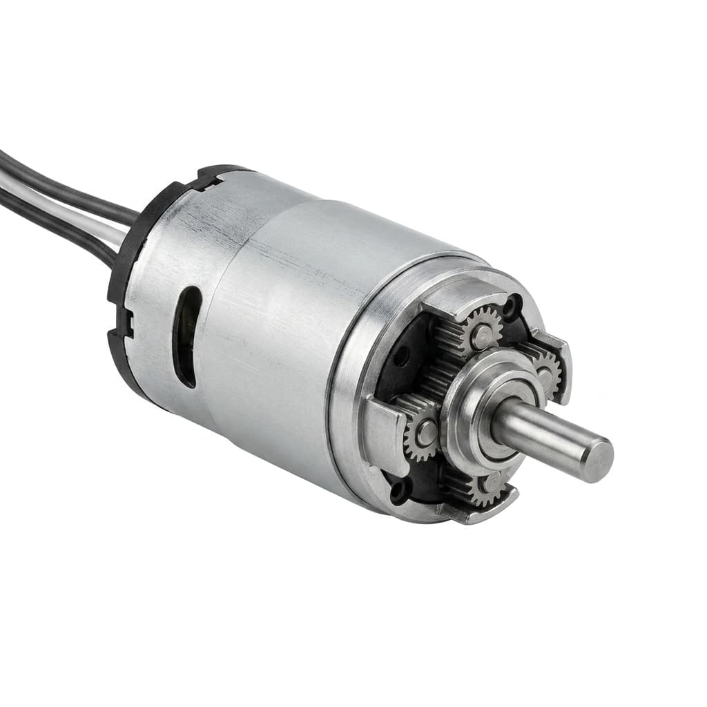
Understanding and Measuring Backlash in Micro Planetary Gearboxes
A practical engineering guide to backlash, arcminutes, static measurement, dynamic reversal behavior, and RFQ data for low-backlash micro planetary gear motor programs.
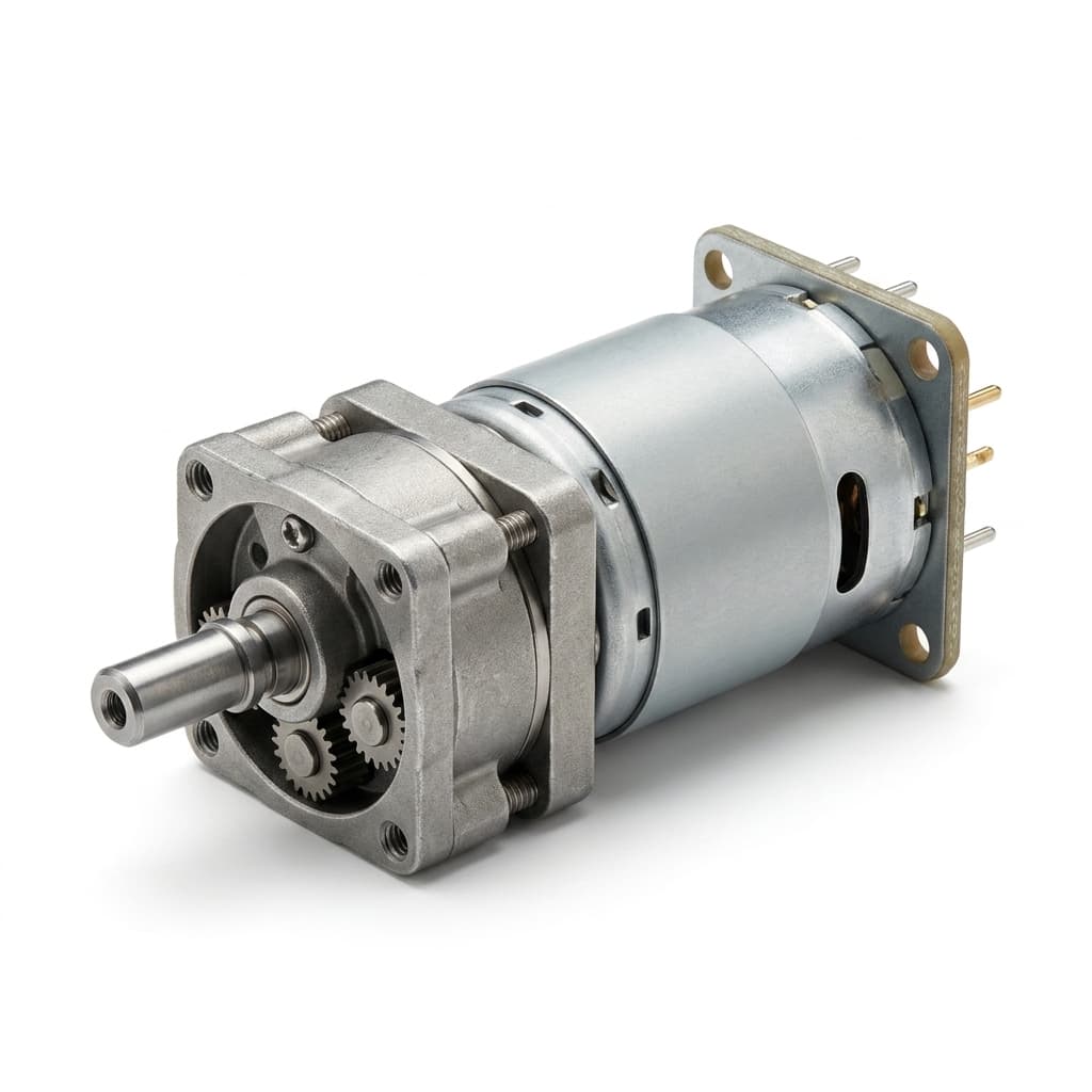
How to Calculate Planetary Gear Ratio and Output Torque
A practical engineering guide to calculating planetary gear reduction ratio, output speed, output torque, efficiency losses, stage count, and RFQ data for micro planetary gear motor projects.
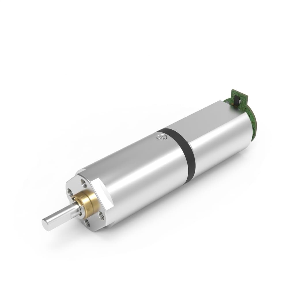
Coreless vs. Brushless Micro Planetary Motors: Which One to Use?
An in-depth engineering comparison between coreless DC and brushless DC (BLDC) micro planetary gear motors, including TCO, lifespan, and control complexity.